

stickshift
New member
- 4
- 3
- 3
- Location
- Grass Valley, Ca
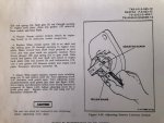
I posted this on another thread, then I saw the generator forum. This subject has been beat to death before, but the only fix I've seen is to adjust the starter lock-out points. I've owned my MEP-003A for over 10 years. The last couple years the starter will re-engage after the engine starts, thus grinding the starter gear on the flywheel. It will also occasionally engage when I shut the unit off and the engine is winding down. . This drives me nuts because I know it is damaging the gears although it cranks fine. I do have a TM and I did follow the starter lock-out setup and the lockout points are set at .040 when running. The crazy thing is that I can sometimes, but not always, engage the starter by turning the switch to "start" when the engine is running and the point are completely open. I can do this even with the connector to the points un-plugged. This should be impossible with the points open, right? My unit was manufactured 1/87 and I have the older version starter with the bendix lever on top. My only thought is that there's something like a minor short in the starter itself. I read in the manual that there is a version II starter that has gear reduction and I'm thinking of ordering one, but I don't want to ruin it with this problem going on. By the way, are the spur gears still available for these older starters? I'm afraid to pull it and look, but I'm sure it's damaged and I would hate to get rid of it if it's repairable. Thanks for any responses. Here's the point setup procedure I used.
Attachments
-
 91.2 KB Views: 16


