• Steel Soldiers now has a few new forums, read more about it at: New Munitions Forums!

  • Microsoft MSN, Live, Hotmail, Outlook email users may not be receiving emails. We are working to resolve this issue. Please add support@steelsoldiers.com to your trusted contacts.

MEP 003a Hertz question

fastbackperry

New member
22
0
0
Location
auburn washington
Thank you in advance for diagnosing my Hertz question.

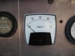
I recently picked up a 003A which runs great and generates power great. The voltage gauge is at 240 but the hertz gauge doesn't work consistently. Only once have I been able to adjust engine rpm to achieve 60 hertz. I know that idling these is not good as I have another one hooked up to the house that works great. I noticed when I shut the generator down and the engine rpm's were coming down that the hertz gauge rose as the rpms came down then dropped as the engine came to a stop. My other 003 has not been consistent but usually works fine especially when I power the house. I've cleaned the ground lug on the unit as William at Delks suggested but no change. He told me that I should have 5 volts direct current at the gauge if I am remembering correctly. I'm seeing 3-4. Any help of what I should test or look at would be appreciated. Once I get this fixed I plan to sell it but don't want to sell it if something is wrong. Thank you again in advance.

Perry
 

Isaac-1

Well-known member
1,970
48
48
Location
SW, Louisiana
Frequency transducers are a common problem on the MEP-002a and MEP-003a generators, unfortunately they are nearly impossible to find and very pricey if you do find one. There are size correct no external transducer needed frequency gauges available, unfortunately the best price I have found on these is around $175-$200. A bit much to pay in my opinion when you can get the same / better results with a under $20 digital display Kill-A-Watt P4400 plugged into an auxiliary outlet.

Ike
 

Triple Jim

Well-known member
1,373
277
83
Location
North Carolina
They can be erratic if very far from 60. As I slowly speed my 003A up from its lowest engine speed, the frequency meter goes through a couple zero to full scale swings. Then as I get near 60 Hz it starts behaving normally.
 

Suprman

Well-known member
Supporting Vendor
6,848
664
113
Location
Stratford/Connecticut
I find that once my 003a has warmed up and has at least a 20 percent load on it then freq shifts smooth out. The panel meter reads around 65hz when it is actually producing 60hz I use my fluke meter.
 

PeterD

New member
622
6
0
Location
Jaffrey, NH
They can be erratic if very far from 60. As I slowly speed my 003A up from its lowest engine speed, the frequency meter goes through a couple zero to full scale swings. Then as I get near 60 Hz it starts behaving normally.
It is possible you are seeing false reading based on harmonics of the generator output frequency. If this is the case, you'll see one at 30 Hz (second harmonic), and another at 15 (third harmonic) and technically one could even see the fourth harmonic at 7.5 Hz but that's unlikely.)
 

Suprman

Well-known member
Supporting Vendor
6,848
664
113
Location
Stratford/Connecticut
I always though harmonics were doubles of the initial frequency. 60hz has 120hz first harmonic 240hz second harmonic. With communications equipment you can see harmonics on a scope or spectrum analyzer. I have no experiance with them this low in freq though.
 

Triple Jim

Well-known member
1,373
277
83
Location
North Carolina
Peter's referring to the second harmonic of 30Hz showing on the meter. The 3rd harmonic of 20 Hz would be 60 Hz, 4th of 15 Hz, etc., but I don't think the speed adjustment on an 003A will go low enough to reach 900 rpm, which would give 30 Hz. Mine certainly won't.
 

Rapracing

Member
271
0
16
Location
Western Pennsylvania
. A bit much to pay in my opinion when you can get the same / better results with a under $20 digital display Kill-A-Watt P4400 plugged into an auxiliary outlet.

Ike
I was going to get one of these but it says Max voltage 125. I know it should not go over that but if it does I assume it will destroy it??

Our power company has been know to have a consistant voltage at times of 127-128.
 

Ray70

Well-known member
2,413
5,244
113
Location
West greenwich/RI
If you want a permanantly installed gage solution, Myself, Storman, CDR and a bunch others have used the $19 digital panel mount Hz/Volt gages from flea-bay with good results. http://www.steelsoldiers.com/showthread.php?114272-Percent-rated-current-gauge they will do 40-70 Hz and I think up to 300V. Can be mounted in place of the original Hz gage ( if you make a simple adapter plate) and wired to the OEM volt meter with just 2 wires, then it will read what ever voltage you set the machine for as well as Hz. Heck for $19 you could even mount it in a little box with a plug or cord and plug it into your courtesy outlet if you run multiple machines and are afraid of cooking a Kill-a-watt in an overvoltage situation. But for a simpler solution for multiple units, I wouldn't worry about the 125V rating on the kill-a-watt, they probably just mean that it's designed for 125V use and not 240V, but the 5-15P plug should make that pretty obvious.
 

Ray70

Well-known member
2,413
5,244
113
Location
West greenwich/RI
Hi Perry, Yes there is low DC voltage going to the Hz gage but I'm not sure exactly what it should be. I know William Delk told you 5v but I thought it was more like 2-3v. I have an intermittently bad transducer and a good gage sitting here on my desk at work and when its working correctly I'm seeing 3VDC. The gage works off a microamp signal, so exact voltage may not be that critical, the amperage through the gage would be the critical factor. At 60Hz you should have 100uA across the gage. I'm not an electrical expert, so maybe someone else can better explain the volt/amp relationship as it pertains to the Hz gage. My gage would occasionally go haywire from the generator's vibration so something inside the transducer is intermittent, but its a partially potted component so it can't be opened and repaired. It was easier to replace everything with a $20 gage than to locate and replace the transducer. If you want to test your transducer/gage just remove them and attach a cord to the 1 and 2 terminals on the AC side of your transducer, then attach you gage to the +/- terminals. Plug the cord into an outlet and see what happens. If it doesn't read 60Hz try tapping on the case of the transducer and watch for spikes on the gage. Also you can check the current flow to the gage and see if you're getting 100uA but you will need a meter with a microamp scale because that is .0001 amps, too small to read on a regular meter.
Ray
 

PeterD

New member
622
6
0
Location
Jaffrey, NH
Peter's referring to the second harmonic of 30Hz showing on the meter. The 3rd harmonic of 20 Hz would be 60 Hz, 4th of 15 Hz, etc., but I don't think the speed adjustment on an 003A will go low enough to reach 900 rpm, which would give 30 Hz. Mine certainly won't.
Sorry, I wasn't clear, I referring to those 'peaks' we see when shutting down the generator. As the engine slows down, at half RPMs (900 RPM), the unit is running at 30 Hz, and at 1/4 RPMs (about 450 RPM) it would output 15 Hz power.
 
Top
AdBlock Detected

We get it, advertisements are annoying!

Sure, ad-blocking software does a great job at blocking ads, but it also blocks useful features of our website like our supporting vendors. Their ads help keep Steel Soldiers going. Please consider disabling your ad blockers for the site. Thanks!

I've Disabled AdBlock
No Thanks