• Steel Soldiers now has a few new forums, read more about it at: New Munitions Forums!

  • Microsoft MSN, Live, Hotmail, Outlook email users may not be receiving emails. We are working to resolve this issue. Please add support@steelsoldiers.com to your trusted contacts.

MEP-004 Starting problems

Dreynolds

New member
4
0
0
Location
Burlington Ky
My MEP004 will not crank at start switch. I have with some help trouble shot as far as I can without help.

Here is where I am.


I am able to start the generator with run switch on and battle short on by shorting starter. With battle short off will not start. Test lamps all clear with exception of oil pressure with BS off.


With BS on, I get a low fuel lamp on but generator will start no power generation though.


With BS off, no lights but won't crank. Tested run switch and 24volt is being applied.


I'm fairly sure that I have a error somewhere not allowing generator to start unless I apply battle short and jump starter. But not very sure where to look.


Any and all help appreciated.

signed Noooby. LOL
 

1800 Diesel

Member
768
25
18
Location
Santa Rosa County, FL
1st question--do you have the TM? If not, DL it from this site. If yes, then did you test the start/run/stop (SRS) switch per TM instructions? I see where you mention .."24 volt is being applied", but I'm confused when you said you have to jump the starter, that implies the old screwdriver trick or a remote start switch across the 24v starter terminal & solenoid. So are you saying the start/run/stop switch is getting 24 volts but it's not being sent [via the correct terminal on the SRS switch] to the solenoid when the switch is placed in start position?

WRT low fuel light, have you filled the main tank and then run the fuel pumps (via BS switch) to fill the day tank? Also, verify the fuel selector valve is pointing to "set" IIRC. I believe the onboard tank setting is facing toward the battery/radiator end.

On the no power issue, did you flash the field at start-up? Is engine spinning at 1800 RPM for 60hz? Are the freq & AC volt meters showing anything?

For us to help, you need to provide a little more info and also get into the TM for some spare time reading and learning.

Lots of gremlins here--attack one at a time and move to the next...

Kevin
 
Last edited:

Dreynolds

New member
4
0
0
Location
Burlington Ky
Clarification

So as I understand it from reading manuals, generator will not start normally with battle short on. I am able to start and run engine with battle short on by jumping starter. Also the generator should not produce power with battle short on. I have tried holding starter switch up and trying to energize but will not produce power.

With it off it will not start even shorting starter. It will turn over by shorting but will not start. when holding in start fuel pumpm runs and lights come on but does not turn over. I have tested all contacts on start switch and they all have 24v when switch is in start position.

I have filled and have full fuel tank and its pumping as needed.
 

212sparky

Well-known member
1,822
38
48
Location
Monroe/ Ohio
Battle short should keep it producing power untill there is no oil or no fuel. It over rides all the safety shut downs. Have you checked that you have power to the solenoid on the starter? It may just be a bad solenoid. I dont have my genset in front of me so i cant look at the schematics of the manual. I can tomorrow tho.
 

1800 Diesel

Member
768
25
18
Location
Santa Rosa County, FL
So as I understand it from reading manuals, generator will not start normally with battle short on. I am able to start and run engine with battle short on by jumping starter. Also the generator should not produce power with battle short on. I have tried holding starter switch up and trying to energize but will not produce power.

With it off it will not start even shorting starter. It will turn over by shorting but will not start. when holding in start fuel pumpm runs and lights come on but does not turn over. I have tested all contacts on start switch and they all have 24v when switch is in start position.

I have filled and have full fuel tank and its pumping as needed.
1st, my bad on the fuel selector valve--I had missed where you were able to actually start & run the engine. WRT the BS switch being on during starting, since it's not the normal start-up procedure I haven't attempted that action, but I don't believe the BS switch being on will prevent the starter from being energized via the SRS switch. Wednesday I'll go check a couple I have in the shop to confirm or dispute the effect of the BS switch being on.

Going back to the SRS switch, I also haven't attempted to test voltage in the start position (since the units I have would be starting up) but I'm thinking all terminals are not supposed to have 24v at that position. As I mentioned previously the TM has a straightforward 3-step test for continuity or open in each of the switch's position (start, run or stop). Each of the 12 terminals is numbered and the TM provides open or continuity status required between various pairs of terminals. I just did this test on one I'm working just a couple nights ago. At a minimum you should check for 24v at the starter solenoid while a helper is holding the switch in start position.

Another item I just noticed--are you saying all fault indicator lights come on when you hold switch in start position? If so, that is not standard. The fault indicator lights (red bulbs RH side of cubicle) should only come on when you depress the panel switch to "test". Prior to engine running but with start switch in run position (and of course DC breaker pushed in), the oil pressure bulb will be lit but no others unless you have a problem (like I did a couple days ago on the under freq light staying on).

Edit--I tried starting "#3 MEP-004A", new to me unit I've just completed the pre-start maintenance & check-out work on & attempted to start with the BS switch on and no-go. Also confirmed per TM: "The battle short switch also locks out the starter
circuit." As I always say--learn new things every day! :)
 
Last edited:

1800 Diesel

Member
768
25
18
Location
Santa Rosa County, FL
Confirm the day tank has fuel, that the day tank's float switch (which signals that it has fuel) is working correctly.
Peter,

If he can jump across the solenoid and start the engine, that tells me the day tank has fuel since it has to gravity feed through the secondary filter and then flow to the IP--unless it was a one-time short run on residual fuel in the fuel line & IP body & once that was burned, the engine shut down. If he can get the engine started and it runs indefinitely, then the fuel system is primed & vented. Do you agree?

On the float switch, there could still be an electrical problem with the diodes in the day tank rectifier assembly. The TM has a quick test for these also. I suspect the float switch is good as they seem to be of simple design and not prone to failure.

Kevin
 

PeterD

New member
622
6
0
Location
Jaffrey, NH
Peter,

If he can jump across the solenoid and start the engine, that tells me the day tank has fuel since it has to gravity feed through the secondary filter and then flow to the IP--unless it was a one-time short run on residual fuel in the fuel line & IP body & once that was burned, the engine shut down. If he can get the engine started and it runs indefinitely, then the fuel system is primed & vented. Do you agree?

On the float switch, there could still be an electrical problem with the diodes in the day tank rectifier assembly. The TM has a quick test for these also. I suspect the float switch is good as they seem to be of simple design and not prone to failure.

Kevin
Yes, I was thinking it was running on what fuel was left in the filter and lines. The idea of the float switch was to prevent draining the filters and air-locking them, I'd think.
 

1800 Diesel

Member
768
25
18
Location
Santa Rosa County, FL
Yes, I was thinking it was running on what fuel was left in the filter and lines. The idea of the float switch was to prevent draining the filters and air-locking them, I'd think.
Agree--On these units, I've gotten into the habit of disconnecting the fuel hose from the inlet side of the secondary filter. This confirms day tank is getting fuel and also you can observe flow rate. Sometimes I find restriction (from crud) in either this hose or the small NPT-JIC fitting on the day tank.

Kevin
 

1800 Diesel

Member
768
25
18
Location
Santa Rosa County, FL
My MEP004 will not crank at start switch. I have with some help trouble shot as far as I can without help.

Here is where I am.


I am able to start the generator with run switch on and battle short on by shorting starter. With battle short off will not start. Test lamps all clear with exception of oil pressure with BS off. I'm fairly sure that I have a error somewhere not allowing generator to start unless I apply battle short and jump starter. But not very sure where to look.

Any and all help appreciated.

signed Noooby. LOL
Interesting coincidence--I just started working on our "#3" MEP-004A and discovered I was having a similar starting problem. In this case though I seem to have a starter dragging or maybe some bad windings inside the starter. Also noticed the start switch would "seem" to run only the fuel pumps when placed in start position, but it fact the starter was getting current to the solenoid but the starter was refusing to turn (probably pulling a bunch of amps too).

Have to do a road trip early in the morning so it's all-stop for now but when I return I'll be pulling the starter & tearing it down to see what I can find. Also will be going through the TM procedure on testing the S/R/S switch like I had suggested to your earlier...will report findings in a couple days.

Kevin
 

Dreynolds

New member
4
0
0
Location
Burlington Ky
Made some progress

So I have progressed... a little.

I found that the starter relay in the big box on top was stuck. WOW that was a ton of work to get out!

I now can hit start switch without BS turned on and engine starts.

Now the bad....

Engine starts and runs but when I let off of start switch is imediately shuts down.

I did have the bright idea to hit BS switch while holding start switch and then letting off start and engine continues to run.

Now acording to trouble shooting steps in manual, it says there are 3 relays to check ....

Anyone have any incite into which one may be the more likely culprit?

Thanks guys for all your support!

By the way I'm in Cincinnati and have a large dually truck and large trailers so if anyone needs something from ohio autions picked up please let me know!
 

glassk

Active member
998
4
38
Location
Hampton, GA
Prior to start when checking lamps all crear with reset. Strangely when battle short is enabled I get a fuel out light. It is not on when BS is off.
test.jpg
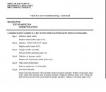
found that the starter relay in the big box on top was stuck. ------not sure about your meaning of stuck,


sounds like it may be in the day tank switches, or wiring . K8 N/O contacts is what fault indicator uses for fuel level and K8 N/C by battle switch to run without k8, so the above table and no fuel in day tank is where I would start. step 6 table above in TM 9-6115-464-12 --in any case I would make sure the cutouts Munchies talked about are working so that the unit is protected , just my thoughts from looking at Foldout 5,


unless the fuel out with B/S on and (Stuck Relay) is a sign of wiring or some other damage
 

Amnon

New member
11
0
1
Location
Raleigh, NC
(four years forward :)
Having a problem with a 004A that was not used in about 5 years. Found out the injection pump was the problem, so got a rebuilt one. The generator started (fresh fuel too) and ran for about an hour. Then the RPM started to go up and down a little (heard it and saw the freq. gauge go up some. So I switched it off. It won't start after that. Checked the fuel in the day tank and it was almost empty. Pumps are pumping all the way to the solenoid at the top of the day tank. Checked voltage in the leads to the solenoid and had 25V, but when the plug is on the solenoid the voltage drops to about 1V. I thought I would put 24V directly to the solenoid but the pins are so deep in it that I did not want to cross the wires, so I noticed the two wires are going to a 1" square box at the back of the day tank, learned it was that Rectifier assembly. On of the terminals on it (there are three) has 25V. Figured out which of the other two was the positive, plugged it in, and shorted the 24V terminal to the positive one for a second. The solenoid clicked and pumps went to town pumping. When the pumps slowed down the generator started. Let it run for 10 minutes and checked the level in the day tank, it was about half full. Shorted the terminals again and it started pumping again.
So it looks like that rectifier is bad, right? What would happen if I leave the terminals shorted, so that the solenoid gets 24V all the time? If it overfills the fuel would go right back into the tank it seems.
Anybody has the schematics for this rectifier (couldn't understand why would they use a rectifier in a DC system anyway, I thought a rectifier takes AC to DC :)
Looked in a few TMs but found no info about it.
Thanks for the help.
Amnon
 

Guyfang

Moderator
Staff member
Moderator
15,978
22,362
113
Location
Burgkunstadt, Germany
You are talking about CR27. It there to prevent voltage from being back fed through the fuel/electric system. CR27 rarely goes bad, but I guess yours is. Were the brass screws loose? Sometimes they get loose, and the terminals move around and touch one another. The schematic is in the manual. There is also a passage on how to test it in the TM's.

I am using a pad, and can't read my TM's right now, but if I remember right, the middle screw should have continuity to both the other screws. Pos. Probe to the middle screw. If you reverse the probes, Neg. to the middle screw, you should get nothing. Any other reading means the CR27 is bad.

If you short past the CR27, your electric fuel pumps will run all the time. Look at the price for a new pump. If your pockets are deep, then run it that way. The only real bad thing about running this way is if you run off AUX fuel. Sooner or later your tank will over fill. If you only run from the set tank, no problem.

Just for laughs and giggles, pull your fuel float switch out, and test it IAW the TM. If the FL1 and FL2 contacts are not working right, the the CR27 will NOT get voltage, to pass on to the L2, (day tank solenoid).
 
Last edited:

Amnon

New member
11
0
1
Location
Raleigh, NC
The schematic is in the manual. There is also a passage on how to test it in the TM's.
Just for laughs and giggles, pull your fuel float switch out, and test it IAW the TM. If the FL1 and FL2 contacts are not working right, the the CR27 will NOT get voltage, to pass on to the L2, (day tank solenoid).
Just spent a few hours looking through the TMs you posted, and by the way THANK you for that great job, and could not find the info. Maybe I blinked?? :) When you have a minute, could you please let me know which TM?
As far as voltage, the rectifier does have 24V on one leg (the one leg that comes from the harness)
Thanks again.
 

Guyfang

Moderator
Staff member
Moderator
15,978
22,362
113
Location
Burgkunstadt, Germany
Open the TM 9-6115-464-12. These passages explain how to test the components.

Go to page (PDF page number) 143. Paragraf 4-24, Day Tank Fuel Level and Low Fuel Cut Off Switch. Read and perform IAW the manual.

Go to page (PDF page number) 144. Paragraf 4-25, Fuel Solenoid Valve and Rectifier Assembly, (CR27). Read and perform IAW the manual.

Go to page (PDF page number) 146. There is a picture of the Rectifier, with a description, showing the screws and colors, to go along with the test procedure in Paragraph 4-25.

Dont assume anything. Test, Test, Test. Instead of draining and refilling the day tank, I would simply take the float out of the Day Tank, and screw the canon plug back in. Then move the float up and down by hand. But then I have done this test probably 500 times, if not more. If it is something new to you, then do it by the book. You cant go wrong then.

Tip #1. The fuel float assembly comes in two versions. Version 1, is the old version. It has TWO floats. It was around a long time, but got replaced by version 2. That doesn't mean ALL gen sets have version 2. They don't. You can still find version 1 if you look hard enough. But the test is the same for both versions.

Tip #2. Pay attention to how you hook up the CR27. Its real easy to get the wires wrong. Take your time. The mounting screw is not the ground for the CR27, so you can hook it up, and let it hang in the wind.

Go to page (PDF page number) 337. It shows FO-1. AC and DC, 15 and 30 KW, 50/60 and 400 Hz, Precise and Utility, Wiring Diagram. On the bottom left side, you will see the wire diagram for the J5 canon plug. Look close, and it shows you what wire goes in what place for the L2, (fuel tank solenoid), the CR27 and the FL-1 and FL-2, (Fuel float switch).
 
Top