- 1,308
- 1,681
- 113
- Location
- Basehor, KS
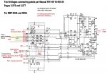
Repair and Test of an A11 Static Exciter Unit for MEP004A/005A
As Kris pointed out, I will be detailing here the tests and results of testing Kris's A11 unit which had a visibly burnt out T2 Transformer during the repair.
There are a total of 5 tests which were performed according to the Manual TM 9-6115-464-34 Pages 3-276 and 3-277
I will post each test with pictures and a more in depth explanation here over the next 2 or 3 days.
I have attached 48 extracted pages of TM 9-6115-464-34 which cover the entire static exciter section for reference and ease of use for the interested reader in pdf format.
The very last post will be in reference to the replacement transformer T2 which we had chosen to start the repair.
So far upfront on T2 - the replacement Transformers Primary Winding's have to be reduced in order to obtain the original Transfers Ratio.
The original Transformer had the fairly bizarre Transfer Ratio of
208VAC to 128VAC = 1.675:1
All most all Center Taped off the shelf transformers today have a Transfer Ratio of
240VAC to 120VAC = 2:1
so, both primary winding's of the replacement transformer will have to be reduced by a total of 0.325 of the total winding count, that is by 0.1625 of each primary winding count since they are connected in series ( 2x 120VAC Center Tapped)
This may sound complicated but it isn't [contact me if you want to buy a already modified T2 Transformer based on a new COTS TR]
It will be next to impossible to find a Transformer today with a 1.675:1 turn Ratio with a VA Rating between 100VA to 300VA
I will also bury a myth which has floated around here on SS for quite a while now connecting a failed T2 Transformer with Sewerzuk's output reconnection board modification to convert the 3 Phase system to a single Phase 208/120VAC system.
Sofar upfront: THE MOD, whether done exactly like in Sewerzuk's Video on Youtube or by forgetting to move the control wires beneath the Output Reconnection Board WILL NOT OVERLOAD / BURN UP T2 Transformer
This conclusion is simply wrong.
I WILL NOT GET INVOLVED IN THE DISCUSSION IF THIS MOD IS GOOD OR BAD TO BEGIN WITH
I CAN TELL YOU ONLY ONE THING: I AM A FIRM BELIEVER IN USING A DELTA / WYE TRANSFORMER TO LET THE IRON DO THE CONVERSION AND BECAUSE I WANT ALL OF THE AVAILABLE POWER TO BE AVAILABLE IN CONVERSION.
Enough said.
The Actual and only cause of T2 burning out is simply the lack of a simple 3 Amp Fuse on the Primary H1 Line.
The directly connected C2 SCR Capacitor fails with age and causes a increasing current draw which is just short of being a short on the secondary side between X1 and X3 which causes T2, because of lack of proper fusing, to burn out over a period of time
This is not an instant failure but one which occurs over a period of time. I would say it could take 15 minutes to 60 minutes once this increased current draw starts to burn out T2
View attachment TM-9-6115-464-34 Static Exciter Section Only.pdf
As Kris pointed out, I will be detailing here the tests and results of testing Kris's A11 unit which had a visibly burnt out T2 Transformer during the repair.
There are a total of 5 tests which were performed according to the Manual TM 9-6115-464-34 Pages 3-276 and 3-277
I will post each test with pictures and a more in depth explanation here over the next 2 or 3 days.
I have attached 48 extracted pages of TM 9-6115-464-34 which cover the entire static exciter section for reference and ease of use for the interested reader in pdf format.
The very last post
So far upfront on T2 - the replacement Transformers Primary Winding's have to be reduced in order to obtain the original Transfers Ratio.
The original Transformer had the fairly bizarre Transfer Ratio of
208VAC to 128VAC = 1.675:1
All most all Center Taped off the shelf transformers today have a Transfer Ratio of
240VAC to 120VAC = 2:1
so, both primary winding's of the replacement transformer will have to be reduced by a total of 0.325 of the total winding count, that is by 0.1625 of each primary winding count since they are connected in series ( 2x 120VAC Center Tapped)
This may sound complicated but it isn't [contact me if you want to buy a already modified T2 Transformer based on a new COTS TR]
It will be next to impossible to find a Transformer today with a 1.675:1 turn Ratio with a VA Rating between 100VA to 300VA
I will also bury a myth which has floated around here on SS for quite a while now connecting a failed T2 Transformer with Sewerzuk's output reconnection board modification to convert the 3 Phase system to a single Phase 208/120VAC system.
Sofar upfront: THE MOD, whether done exactly like in Sewerzuk's Video on Youtube or by forgetting to move the control wires beneath the Output Reconnection Board WILL NOT OVERLOAD / BURN UP T2 Transformer
This conclusion is simply wrong.
I WILL NOT GET INVOLVED IN THE DISCUSSION IF THIS MOD IS GOOD OR BAD TO BEGIN WITH
I CAN TELL YOU ONLY ONE THING: I AM A FIRM BELIEVER IN USING A DELTA / WYE TRANSFORMER TO LET THE IRON DO THE CONVERSION AND BECAUSE I WANT ALL OF THE AVAILABLE POWER TO BE AVAILABLE IN CONVERSION.
Enough said.
The Actual and only cause of T2 burning out is simply the lack of a simple 3 Amp Fuse on the Primary H1 Line.
The directly connected C2 SCR Capacitor fails with age and causes a increasing current draw which is just short of being a short on the secondary side between X1 and X3 which causes T2, because of lack of proper fusing, to burn out over a period of time
This is not an instant failure but one which occurs over a period of time. I would say it could take 15 minutes to 60 minutes once this increased current draw starts to burn out T2
View attachment TM-9-6115-464-34 Static Exciter Section Only.pdf
Last edited: