• Steel Soldiers now has a few new forums, read more about it at: New Munitions Forums!

  • Microsoft MSN, Live, Hotmail, Outlook email users may not be receiving emails. We are working to resolve this issue. Please add support@steelsoldiers.com to your trusted contacts.

MEP-004A parts, and problems

joshgar8

New member
51
0
0
Location
Nashville, Tennessee
Joe,

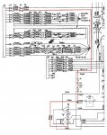
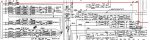
I removed both the voltage regulator/exciter and the control box. I took a look into both items and could not find and visible problems. As for the Terminal Board 101, I found it. With the control box out of the genset, I cannot check for 24v but I did check continuity between J2-terminal-R and lug number 11 and it was good, no open wire.

I can actually check continuity from J2-terminal-R all the way through to the test fault plug terminal-A where I am suposed to have 24v wich I have contunity, BUT my intial check for voltage did not have 24v. That tells me the problem is from the plug in J2 plug back to the s2 switch, because I had 24v on lug 3 on S2. Can we check to make sure that the wire from lug 3 on S2 goes directly to terminal 11 on terminal board 101?

Does this sound correct and make any sense?

Thanks,
Josh
 

Crash_AF

Active member
1,530
7
38
Location
Colorado Springs, CO
Sure, here's an extract of that circuit. The red line is the path from S2-3 to the fault panel (A9). It shows all the components that the power passes through on the way.

So to make sure I'm understanding, you tested for continuity between J2-R and P6-A and there is continuity? While you've got it unplugged, can you check between P2-R and S2-3?

Later,
Joe
 

Attachments

joshgar8

New member
51
0
0
Location
Nashville, Tennessee
That was my next move, checking for continuity between, P2-R wich is the main wiring harness plug out of the control cubicle going to the control box, and the S2-3 which is the strart/run/off lug 3 where I had 24v. that will tell me if there is a open wire . Based on the info that we have gathered, this has to be the problem. Im planning on doing that test today.

Thanks,
Josh
 

joshgar8

New member
51
0
0
Location
Nashville, Tennessee
Joe,

I just got down checking the wires we discussed prior. I do have good wires all the way from the S2 thru the control box out to the fault panel. It doesnt make any sense why I didnt have 24v unless something was loose and working on it has got it back in order. What wire is the gound going to that fault box, or does it groung thru the frame of the box to the frame of the gen? At this point, I think I should have 24v if I put it all back together, but I want to double check the ground on that fault box.

Thanks,
Josh
 

Crash_AF

Active member
1,530
7
38
Location
Colorado Springs, CO
You should have 24V at P12-A regardless of what the ground is doing because you're grounding the multimeter separate of the plug.

But, the ground for the fault box runs from P12-B through wire P66A to P6-B then to the DC Relay Assembly terminal 3 which is in the control box. Inside the relay assembly, it runs through K5 relay's normally open contacts.

Where the red goes off the sheet, that goes straight to the Special Relay Box Ground. So there should be continuity to ground at terminal 15 on the DC Relay Assembly.

Later,
Joe
 

Attachments

Last edited:

joshgar8

New member
51
0
0
Location
Nashville, Tennessee
Joe,

I checked P12-B and directly to ground on the box frame and I had continuity. At this point everything is checking out perfect. Do you think the next move would be to install both boxes back in and see what I have got?

Thanks,
Josh
 

Crash_AF

Active member
1,530
7
38
Location
Colorado Springs, CO
Yea, I'd give it one good final inspection and bolt it back in. Doublecheck all the connections to make sure the canon plugs are tight. Push them in, tighten the ring, then push it in again and try to tighten the ring again until they are seated good and tight.

Later,
Joe
 

joshgar8

New member
51
0
0
Location
Nashville, Tennessee
Joe,

When I did my final inspection putting everything back together, I found one broken cannon plug. It looked freshly broken. The broken plug was the plug comming from the three remote connections in the control cubicle. It was also plugged into the wrong socket from the hertz place. I took photos before I tore it all apart to ensure it went back together right, assuming it was right when I got it back from hertz. Not only was the two plugs connected wrong (remote plug into fault box plug and vault box plug into the remote plug) The complete control box was in backwards. I got everything hooked up correctly and guess what........ the fault indicators work. I am not to worried about the broken cannon plug, It was just the outer aluminum ring around the pins of the plug where the index slot WAS cut. I got it lined up correctly without the index slot, i was very careful plugging it in, and the good part was it is in a pretty decent place where i could see all the pins so I know they are in correctly. Pretty good odds I will never need the remote concetions anyways, If so I will replace the plug.

Now my hertz gauge is still not responsive and my voltage is still on the high side. I havent had time to take a look regaurding the Hertz gauge. Do you have any opinions on where to start with that one? If we can get that prolem solved, we will be back to where I was before I took it to hertz rentals for repair. I also got to get more bolts for the fuel filter housing, the mechanic though it was nessecary to take the housing away from the mount and lost all the bolts so its just dangling. I would guess that the bolts are in the same place is 4 out of the 6 that holds the control box in place and 3 out of the 6 that holds the voltage regualter in place....... What a great mechanic, I would hate to think in a state of emergency people and places like hospitals depend on this guy. If anybody needs his info to stay away from him, shoot me a pm...


Thanks,
Josh
 

Crash_AF

Active member
1,530
7
38
Location
Colorado Springs, CO
Well, I'm glad that you've gotten the fault box put back right at least.

You say the frequency is non-responsive. Is your set a MEP-103A on the dataplate or is it a MEP-004A (OR AAS if it has the acoustic kit on it) If it's a MEP-004A, the frequency is adjusted with the manual throttle under the control panel, the knob on the panel won't do anything and is just there (don't ask me why... it's a waste of govt money to add stuff that's non-functional if you ask me).

I would also go through and verify ALL of the other cannon plugs to make sure they are not swapped around.

If your multimeter has a frequency (Hertz) function, switch to that and plug it into the convenience receptacle to see if it's a gauge problem, or a generator problem.

Later,
Joe
 

PeterD

New member
622
6
0
Location
Jaffrey, NH
Well, I'm glad that you've gotten the fault box put back right at least.

You say the frequency is non-responsive. Is your set a MEP-103A on the dataplate or is it a MEP-004A (OR AAS if it has the acoustic kit on it) If it's a MEP-004A, the frequency is adjusted with the manual throttle under the control panel, the knob on the panel won't do anything and is just there (don't ask me why... it's a waste of govt money to add stuff that's non-functional if you ask me).
I think you'll find it is there to allow the control panel to be used for multiple applications. Allows for compatibility between the utility and the precise models.
I would also go through and verify ALL of the other cannon plugs to make sure they are not swapped around.
It is unfortunate that some of the cannon plugs are in fact identical and can be easily be swapped if one is not careful.
If your multimeter has a frequency (Hertz) function, switch to that and plug it into the convenience receptacle to see if it's a gauge problem, or a generator problem.

Later,
Joe
The frequency meter consists of a 'module' inside the control panel that takes 120 volts and converts it to a value that can be used with the meter. Technically it is a tachometer. I may have a spare if the OP finds his is bad. I'd start, however, by measuring the frequency as you suggest, and making sure it is not reading correctly. The module is sealed, and I don't think it can be disassembled. I also have some digital frequency meters that work well in this application, but they are not standard so if one is doing a restoration it won't look right.
 

joshgar8

New member
51
0
0
Location
Nashville, Tennessee
Joe,

My set is a MEP-004AAS. I was noticing while trying to figure out the fault box when I would start it up, the hz gauge was kinda jumpy from 60hz to 48hz which is where it goes with everything off. It would bounce around some. Now it does not respond at all. It just stays on 48hz. I can pull the rpms up and down and no movement out of the gauge. I am going to try and round up a handheld multi meter to check it like you recomended. The fluke I have been using does not not have the option to check it. Thanks again for your help to get this thing back in good working order.

Peter,

You are correct about the cannon plugs being able to go to the wrong place. I was not very confident in being able to put it all back together so I got the digital camera and took about 25 pictures in every angle to verify I was putting it back together the way it came apart. Little did I know the mechanic ahead of me didnt do the same. After I got all the wires secured like they was supposed to be to the eyelets on the mounting bolts that he lost I realised that none of my wires was long enough to plug in. So thats when I found out he had it in backwards and the wires plugged into the wrong spot.

I took a look at the back of the hz gauge. Can I test the two wires that feed it to see if I am getting the correct voltage to the gauge from the module? If I am getting 60hz out of the unit via a handheld DVOM what kinda voltage should I expect going into the hz gauge?


Thanks guys for all the help,
Josh
 

PeterD

New member
622
6
0
Location
Jaffrey, NH
[FONT=&quot]The gauge (all d'Arsonval [FONT=&quot]meter movements) are typically current driven, not voltage (voltages can be specified, however). I'll see if I can find the spec for this meter.

Do put a VOM (volts scale will work, though the volts will be very low) and see what you get. Also locate the black box for the frequency meter, it should have four terminals on it, check for 120 volts on the input terminals, and see what you have at the output terminals too...

Heck, you could (if you wanted) take the sender/transducer module (that black box...) and connect it to a 120 volt supply such as your house, and the meter should read dead on at 60 Hz.

I just hope that the mechanic's errors didn't damage something...

[/FONT]
[/FONT]
 

joshgar8

New member
51
0
0
Location
Nashville, Tennessee
I have not been able to locate a DVOM with freq. reading on it. I did check to make sure the wires was good from the transducer to the HZ gauge and they was. I checked the AC voltage going into the transducer and it was 147. I know that is high, but that goes back to my first problem that promoted me to take it somewhere for repair.

My next step is to take both the transducer and the gauge out and I am going to test it in the house plug to see if that setup is working correctly, im sure one of the two is the problem, and I am wondering if the high voltage has fried the transducer.
 

joshgar8

New member
51
0
0
Location
Nashville, Tennessee
I just checked the transducer wired up to the gauge plugged into my house outlet. Its was dead nuts on 60HZ no jumping of the needle on the gauge or anything. If I have 147 volts to the transducer and the wires from the transducer to the gauge are not bad where do I go from here? When I took it all apart none of the wires had a lose connection.
 

Crash_AF

Active member
1,530
7
38
Location
Colorado Springs, CO
Sorry for the delay in getting back to you, I was out of town until today.

On to your problem at hand. Since you've isolated that the meter is working properly, I'm going to assume that there is something keeping the set from producing power properly. My guess is the voltage regulator/static exciter.

Have you flashed the field yet? After the set starts, hold the start switch in the up position for a few seconds to see if the frequency comes up. Don't worry about hurting the set, there is a cutout switch that shuts the starter down after the engine starts. See if that brings the frequency up. If it doesn't, we need to start testing the VR.

It is covered in the -34, Section 3-92, page 3-264

Later,
Joe
 

joshgar8

New member
51
0
0
Location
Nashville, Tennessee
Joe,

I hope you had a great trip and great holiday weekend. I havent been spending much time on the gen set due to the holiday, and I am going to be out of town myself all next week so we wont get much progress till the 13th or so.

I tried fashinging the field, everything seems to be working as it was before I took it to HERTZ as far as the voltage output. It remains high in all the settings. I checked the voltage going into the transducer feeding the HZ gauge, and it was 147v when it was suposed to be 120v, but I think that is from the gen set putting out to much voltage in general. I have not been able to locate anything to manually check the HZ the unit is putting out through the conv. outlets. I am planning on putting the HZ gauge and transducer back in because I wired it up and it checked out good when it was plugged into my home outlet.

Thanks for the help,
Josh
 

Crash_AF

Active member
1,530
7
38
Location
Colorado Springs, CO
Yea, looks like the VR is the next teardown and inspect project. If you don't know electronics very well, you might want to find an electronics repair shop to take the VR to, print off and take pages 3-264 through 3-284 with the VR and ask them if they can perform the tests as outlined on those pages.

Later,
Joe
 

joshgar8

New member
51
0
0
Location
Nashville, Tennessee
Joe,

I havent abandoned the gen set, just havent found time to work on it due to preparing for a trip. AFter I get back in town I am going to find somewhere to take it to and do as you said. At this point I think thats the best. I thought the VR was good due to the mechanic from hertz telling me so, but his other work proved me wrong.... I will update this in a couple weeks after the trip and when the elec shop has taken a look at it.

Thanks,
Josh
 

joshgar8

New member
51
0
0
Location
Nashville, Tennessee
Joe,

I rounded up a DVOM with a HZ meter. I just checked the gen set and it puts outs 60HZ as it should consistantly. It also adjust by the throttle as it should from 48hz on up to 72hz or so. I have the throttle set at 60HZ, and while getting it dialed in the HZ gauge started working when it wanted to, almost like a loose connection. I am still going to take the VR to the elec. shop to get them to take a look, hopefully if they find one single problem, it will saolve all the problems.

Thanks,
Josh
 
Top
AdBlock Detected

We get it, advertisements are annoying!

Sure, ad-blocking software does a great job at blocking ads, but it also blocks useful features of our website like our supporting vendors. Their ads help keep Steel Soldiers going. Please consider disabling your ad blockers for the site. Thanks!

I've Disabled AdBlock
No Thanks