- 123
- 2
- 18
- Location
- Washington NC
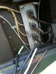
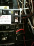
Setting voltage up to 240 should not make outlet put out 135 140. check the voltage at the connection lugs. your gauge could be off that much.
Steel Soldiers now has a few new forums, read more about it at: New Munitions Forums!


Thanks for the input. I'll have to check this more when I get back in town. I will be doing the TS soon as wel as the gen plug on the side. Need to swap out the plug on the genset to a newer type of plug.either could be off but the unit one is not very reliable. just good to double check. I checked my 005 today and it was putting out 125 at utility outlet with it set at 240. I run mine at 220 all the time as I feed a building that is not 3 phase with that unit. and get 120 ish out of other legs no problem.
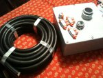
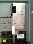
100A cable? Won't welding cable work sufficiently for that? You can buy it by the foot from a tractor supply store or some big box stores.I'm figuring the the wiring/conduit, the generator plug in box, and mounting the transfer switch and gathering up the materials to do most of the work besides the TS install. I'll have a elec friend do that.
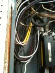
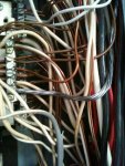
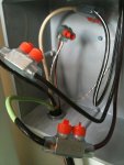
I am having a hard time finding a replacement plug for the generator that attaches to the lugs. Maybe I need to make a custom one? Also hard to find 100 amp cables to run from the gen to the outside plug.
Thanks Ike, will do. Much appreciated!Just off the top of my head, it seems 15KW should be in the 70 amp range at 120/240V single phase, if so 2/4 SO cord should work for you, maybe even 4/4 SO cord. You might also check out ebay for 75 - 100 amp pin and sleeve connector set that will work for you.
Ike