1800 Diesel
Member
- 768
- 26
- 18
- Location
- Santa Rosa County, FL
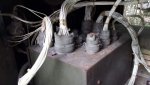
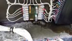
OK for the few of you who work on the water-cooled models, I just did a "1st for me" light-off for this unit & I've got an under-frequency indication but freq meter is reading 60 hz. Tried to reset several times, but no change. Closed the AC breaker and tested voltage & frequency at L1, L2 & L3. All close to 120v and freq at 60 hz. Since it was getting late I didn't want to disturb too many of my fine neighbors so have shut down for the night. One thing I did do was to switch the start/run/stop switch to the start position and when I do that the under freq indicator light goes out.
Forgive me if this is a no-brainer found right in the troubleshooting section of the TM but I needed to get some supper before I dug through the manual. Will be doing that next....thanks for any ideas or comments...BTW, this unit has not been modified (yet) for the single phase re-wire....all components as found except oil & fuel & filters....
Thanks for any help sent,
Kevin
Edit--A quick-look at the schematic shows relay K12 for under freq. Once I locate it on the unit, will swap the relay out with a known good one and retest. Won't be able to run it until this coming Friday though....will report findings.
Last edited: