-
Steel Soldiers now has a few new forums, read more about it at: New Munitions Forums!


MEP 005A 30k parts, where?
- Thread starter zb39
- Start date

More options
Who Replied?brianrbull
Member
- 351
- 9
- 18
- Location
- Casnovia Michigan
On the Alternator Those are spendy when you find them I think I found one for my MEP-006a and they wanted like $500 I ended up getting a 24v Delco adding a 2 belt pulley for less than $125 Now the Injector Pump is a different deal I may have a solution for you .
PM Sent
PM Sent
Last edited:
I had to have my mep-005a IP rebuilt. It was $450. While I was waiting I started looking for a spare. I found one on the web for ~$650.
I will lookup the part number and post it tonight.
Do you need the manuals? They are listed in the Generator Tech Manual forum
http://www.steelsoldiers.com/showthread.php?77624-TM-s-for-Generators
Warthog
I will lookup the part number and post it tonight.
Do you need the manuals? They are listed in the Generator Tech Manual forum
http://www.steelsoldiers.com/showthread.php?77624-TM-s-for-Generators
Warthog
Last edited:
The IP number is:
DBMFC 633-1LK
Surplusman : Search
PM your email address and I'll send the manuals.
Anyone know how to add manuals to the Tech Section?
DBMFC 633-1LK
Surplusman : Search
PM your email address and I'll send the manuals.
Anyone know how to add manuals to the Tech Section?
CGarbee
Well-known member
- 2,448
- 510
- 113
- Location
- Raleigh, NC
If you still need the alternator, send me a PM... I have a spare 005A for the unit we have installed for backup power here at the farm that I know is missing the injector pump, but that may still have the alternator... I'll go look in the morning...
Great score.Warthog thanks, i was looking it over today and found the top tool box....................inside was a brand new still in wrap manual.....i love spoils..
Which manual did you find? I have a total of 6 manuals
TM5-6115-465-10-HR Hand Reciept Manual
TM5-6115-465-12 Operator and Organizational Maintenance Manual
TM5-6115-465-34 Depot Level Maintenance Manual
TM5-6115-626-14&P Direct Support Maintenance Manual w/Parts
TM5-6115-627-14&P Direct Support Maintenance Manual w/Parts
TM9-6115-465-24P Unit, General and Direct Support Maintenance Manual w/Parts
Located in the Generator Tech Manual forum
http://www.steelsoldiers.com/showthread.php?77624-TM-s-for-Generators
Warthog
Last edited:
nofear
New member
- 10
- 0
- 1
- Location
- Indianapolis/IN
Warthog, I just found this, and I posted already, but could I get a copy of some of those manuals you have?
washingtonmountains
New member
- 20
- 0
- 0
- Location
- Skaneateles, NewYork
If you still need the alternator, send me a PM... I have a spare 005A for the unit we have installed for backup power here at the farm that I know is missing the injector pump, but that may still have the alternator... I'll go look in the morning...
Any chance that you would have a spare speed switch, I think it is actually a tach? send me an e-mail if you do. Thanks, Dale
Jim832904
New member
- 18
- 0
- 1
- Location
- Towanda Pennsylvania USA
Searching for TM's for the MEP005A and came across this posting. Would you be willing to email me files on each of these?
Thanks alot
I did get mine running and working on set up as a whole house backup with an ATS. Still sorting out the hand drawn starting circuit I got from the factory engineer. Do you know anything about the J29 Jack in the special relay box and wiring into it for remote starting signal from the ATS?
Thanks again.
Jim
tablerockmtn@epix.net
chadtrees
New member
- 16
- 5
- 3
- Location
- morven, ga
I acquired a mep-005a that won’t produce power. Motor runs strong but voltage gauges do not register. Service outlet has no power output and the three legs register no voltage. I’ve taken the cover off the voltage regulator box and there are some rough looking “capacitors” (I think that’s what they are) on the board.
Is there some other checks I can do to trouble shoot this gen?
Or other things that would cause no voltage?
If it is indeed the voltage regulator. Is there a source for them or possibly someone or some place that can rebuild them?
Thanks for any help.
Is there some other checks I can do to trouble shoot this gen?
Or other things that would cause no voltage?
If it is indeed the voltage regulator. Is there a source for them or possibly someone or some place that can rebuild them?
Thanks for any help.
- 15,900
- 22,176
- 113
- Location
- Burgkunstadt, Germany
Have you downloaded the TM?
You say it will not produce power. Try this. On startup, pay attention to the hertz and AC volt gauge. Do they, on start up, come up for a second or two? Or not move AT ALL. This is important. If they do not move at all, you could have a problem with the S9, (Speed Switch). The S9 has three functions.
1. To kick the starter out at a predetermined speed.
2. Excite the Main AC.
3. Shut the set down if it over speeds.
chadtrees
New member
- 16
- 5
- 3
- Location
- morven, ga
Thanks for the reply.Have you downloaded the TM?
You say it will not produce power. Try this. On startup, pay attention to the hertz and AC volt gauge. Do they, on start up, come up for a second or two? Or not move AT ALL. This is important. If they do not move at all, you could have a problem with the S9, (Speed Switch). The S9 has three functions.
1. To kick the starter out at a predetermined speed.
2. Excite the Main AC.
3. Shut the set down if it over speeds.
I have downloaded TM5-6115-465-12.
I checked to Hertz and A/C gauges this morning and they do not move. (They bounce maybe 1/4” but I think that’s just a result of movement of the machine)
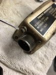
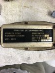
From reading previous post I have the electronic version switch. When I removed it I noticed the hold down bolt wasn’t all the way tightened. Which leads me to believe it’s possibly been removed before. I also noticed there is a small button with a rubber cap on top. I depressed it and reinstalled the sensor but still no results. I’ve attached a photo of my sensor. Referencing the part # 70-1105-13 on my sensor to your previous part #’s for this model they do not match. Could someone have put the wrong sensor in?
I’m reading over the TM now about checking continuity/discontinuity between the pins. I will attempt this today.
Is there other checks I can do?
If the one on my machine is a correct part number should I disassemble it and look for problems inside it or not like the mechanical version and can’t be repaired?
Again thanks for the help!
Update: I preformed continuity/discontinuity as stated in the TM. Results are that all pin combinations had continuity. Even the pin combinations that are supposed to be discontinuity.
Attachments
-
 82.6 KB Views: 10
 -
 93.7 KB Views: 10
Last edited:
- 15,900
- 22,176
- 113
- Location
- Burgkunstadt, Germany
Open to read commentsThanks for the reply.
I have downloaded TM5-6115-465-12. (Do down load the -34 also. All the TM's you need are here in the TM forum, along with a few extra things. Also know, the 004A and 005A are the same-same. About 95 percent compatible, and the TM's are interchangeable. About the only place you need to watch out for is the -24P.)
I checked to Hertz and A/C gauges this morning and they do not move. (They bounce maybe 1/4” but I think that’s just a result of movement of the machine) Are you holding the S1 up long enough? At least 6-8 seconds?
From reading previous post I have the electronic version switch. When I removed it I noticed the hold down bolt wasn’t all the way tightened. Which leads me to believe it’s possibly been removed before. I also noticed there is a small button with a rubber cap on top. I depressed it and reinstalled the sensor, (S9 speed switch) but still no results. (That's the reset switch. Normally it is used to reset over speed.) I’ve attached a photo of my sensor. Referencing the part # 70-1105-13 on my sensor to your previous part #’s for this model they do not match. (There are about 10-15 NSN's and part #'s for a speed switch. Every time I look, there seems to be more. Like weeds) Could someone have put the wrong sensor in?
I’m reading over the TM now about checking continuity/discontinuity between the pins. I will attempt this today.
Is there other checks I can do?
If the one on my machine is a correct part number should I disassemble it and look for problems inside it or not like the mechanical version and can’t be repaired? (Normally its a non-repairable switch. I have repaired a few. Wire broken off inside the switch. Look inside at your own risk. Just be careful opening and closing it. Test it. You do not need to test S9-1 contacts. The gen set turns over and starts. Its S9-2 you need to test. And that's hard if you do not have the right test rig. We made one with a drill and RPM counter. We found a c-plug and hooked up wires and lights, so we could use the drill to drive the switch. At about the speeds that it should change, lights came on or off. A test rig like that is a bunch of work to test your S9, and probably never use it again in your life. So, here is a quick way to see if the switch is sending a signal to the main gen to excite it. Go to TB-16 on the relay table. You hold a multi-meter set to read VDC on the two terminals. Have someone else start the set and hold the S1 in the start position for at least 6-8 seconds. What reading do you get?)
Again thanks for the help!
Last edited:
chadtrees
New member
- 16
- 5
- 3
- Location
- morven, ga
Open to read comments
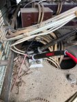
Ok, I believe I correctly tracked down "TB-16". On VDC I got no readings while starting and holding the S1 (I believe is S2 on my gen because S1 is the "Engine Primer" switch) for 6-8+ seconds.Open to read comments
photo of believed to be TB-16?
Attachments
-
 106.5 KB Views: 13
- 15,900
- 22,176
- 113
- Location
- Burgkunstadt, Germany
Correct! Thats TB-16 And yes, S2. I am getting old.Ok, I believe I correctly tracked down "TB-16". On VDC I got no readings while starting and holding the S1 (I believe is S2 on my gen because S1 is the "Engine Primer" switch) for 6-8+ seconds.
photo of believed to be TB-16?
Element #1 is what you need to somehow check. Pin A is +24 VDC. When the S9-1 contacts are as pictured below, you can start/turn over, the engine. At more or less 290-310 RPM, the contacts reverse. Pins A& B are open, and pins A &C are closed. When that happens, the main gen gets initial excitation. And that's what you were looking for when you tested for 24 VDC at TB-16

There could still be a wire problem from J37, (S9 canon plug) to the J6, (Special relay box Canon plug). So get some help. One of you on both side of the Multi-Meter, testing ohms. Go from J37-A to P6-D. Should get continuity. Then from J37-C, to J6-V. Should be continuity.
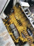
Next comes the A11, (Special Relay box) take all the C-plugs off. Remove the box from the relay table. Open the box, and look at the A5 card, (DC relay card) see if K5 is there. If its tight. Look at the card front and back to see if the card is burnt. Look at the whole box for burnt wires or anything "strange".
chadtrees
New member
- 16
- 5
- 3
- Location
- morven, ga
I went ahead and opened A11. I believe I located the A5 board and it looks old and rough. I still have not been able to determine where K5 is but there is definitely some burnt resistors on the board. I attached pictures of the board.Correct! Thats TB-16 And yes, S2. I am getting old.
Element #1 is what you need to somehow check. Pin A is +24 VDC. When the S9-1 contacts are as pictured below, you can start/turn over, the engine. At more or less 290-310 RPM, the contacts reverse. Pins A& B are open, and pins A &C are closed. When that happens, the main gen gets initial excitation. And that's what you were looking for when you tested for 24 VDC at TB-16
View attachment 847014
There could still be a wire problem from J37, (S9 canon plug) to the J6, (Special relay box Canon plug). So get some help. One of you on both side of the Multi-Meter, testing ohms. Go from J37-A to P6-D. Should get continuity. Then from J37-C, to J6-V. Should be continuity.
Next comes the A11, (Special Relay box) take all the C-plugs off. Remove the box from the relay table. Open the box, and look at the A5 card, (DC relay card) see if K5 is there. If its tight. Look at the card front and back to see if the card is burnt. Look at the whole box for burnt wires or anything "strange".
Bad weather has caught me and had to close it up for the day.
Thanks for you help.
Attachments
-
 102.8 KB Views: 30
 -
 156.2 KB Views: 25
- 108,422members
- 163,717threads
- 2,303,406posts
- 1,156online users