• Steel Soldiers now has a few new forums, read more about it at: New Munitions Forums!

  • Microsoft MSN, Live, Hotmail, Outlook email users may not be receiving emails. We are working to resolve this issue. Please add support@steelsoldiers.com to your trusted contacts.


mep-005a giving me a reverse power warning.

55
7
8
Location
gainesville fl
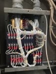
ent to test run the unit with elsa on the way and no cables connected to it at all the reverse power light is on its producing power it just wont let me close the breaker i even unplugged the avr and started it and i still get the same thing while the unit was not even able to make power I'm scratching my head on this one.

what i have dun so far i am able to close the breaker with the battle short switch on and get power no issues but the revers power light comes on as soon as i try to close the breaker it will reset every time then come back on so for some reason the system is thinking it has reverse voltage when it does not.
 

Chainbreaker

Well-known member
1,748
1,834
113
Location
Oregon
You can find the location in the TM's. Since you have a storm on the way I'll save you some time...in the the -24POLD PDF look on pg pg 47 item # 49.

Edit: The procedure to test the relay is in TM 9-6115-644-24 (its the TM just to the right of the -24POLD linked /\ above. On PDF pg 347 is the procedure for testing "Reverse Power Relay".

Guy has all the TM's located in the TM section under the "TM" thread, it's up top of this page across from the search icon just left of it. The TM's are your friend!
 
Last edited:
55
7
8
Location
gainesville fl
You can find the location in the TM's. Since you have a storm on the way I'll save you some time...in the the -24POLD PDF look on pg pg 47 item # 49.

Edit: The procedure to test the relay is in TM 9-6115-644-24 (its the TM just to the right of the -24POLD linked /\ above. On PDF pg 347 is the procedure for testing "Reverse Power Relay".

Guy has all the TM's located in the TM section under the "TM" thread, it's up top of this page across from the search icon just left of it. The TM's are your friend!
ok got them it looks like this is a blow out of the front controll panel but i do not have those relays in there is this actually one of the boxes inside the genset? i see what it is i have a 005a you sent me manuals for a 805 a
 
Last edited:
55
7
8
Location
gainesville fl
i have the manuals for it thanks for letting me know where to look in them im assuming its in the big box with all the connections in 2nd level middle electronics compartment???
ok got them it looks like this is a blow out of the front controll panel but i do not have those relays in there is this actually one of the boxes inside the genset? i see what it is i have a 005a you sent me manuals for a 805 a
ok i found the location of mine in manual TM9-6115-465-24p page 113 it looks different from the one you sent so I bet the test procedure will not be the same now got to figure out how to find that.
 
55
7
8
Location
gainesville fl
ok i found the location of mine in manual TM9-6115-465-24p page 113 it looks different from the one you sent so I bet the test procedure will not be the same now got to figure out how to find that.
ok found the test procedure tm5-6115-465-34 page 253 they call it the tactical relay assembly on this one so is there a more direct way to test this as i do not have access to variable power supplies.
 
55
7
8
Location
gainesville fl
ok found the test procedure tm5-6115-465-34 page 253 they call it the tactical relay assembly on this one so is there a more direct way to test this as i do not have access to variable power supplies.
trying to track down a power supply i can buy or borrow in the event it is bad what would be the best way to bypass it without using the battle short. it looks like i could disconect 7 and 8 and that would kill its power to operate maybe?
 

Scoobyshep

Well-known member
914
989
93
Location
Florida
Just need to bypass the contact that is removing power from the contactor circuit. In the morning when I get to the office ill look at the wiring diagram

Sent from my SM-G973U using Tapatalk
 
55
7
8
Location
gainesville fl
Just need to bypass the contact that is removing power from the contactor circuit. In the morning when I get to the office ill look at the wiring diagram

Sent from my SM-G973U using Tapatalk
So found it it does not visually look bad only thing I saw was this resister discolored but that could just be the coating worn off
 

Attachments

Scoobyshep

Well-known member
914
989
93
Location
Florida
K15 (reverse power relay) uses the NC contact for circuit breaker and a NO contact for the fault indicator. since you have both a fault and the breaker wont close, it leads me to believe that K15 is not in its de energized state
 
55
7
8
Location
gainesville fl
K15 (reverse power relay) uses the NC contact for circuit breaker and a NO contact for the fault indicator. since you have both a fault and the breaker wont close, it leads me to believe that K15 is not in its de energized state
So where should I go with this since it can’t possibly have a revers voltage situation? Your saying that the relay is fine that it’s tripping for some other reason where does it get the signal to trip from and is there a way to bypass it if I can’t fix it in time for the storm.

sorry to keep bothering I’m not really that great at reading the schematics and I found the one with k15 but I might as well be reading Chinese.
 
Last edited:

Scoobyshep

Well-known member
914
989
93
Location
Florida
So where should I go with this since it can’t possibly have a revers voltage situation? Your saying that the relay is fine that it’s tripping for some other reason where does it get the signal to trip from and is there a way to bypass it if I can’t fix it in time for the storm.

sorry to keep bothering I’m not really that great at reading the schematics and I found the one with k15 but I might as well be reading Chinese.
Unless you parallel this unit with another it isn't needed (first thought is reverse rotation, but its more of an anti motorizing relay {what happens when 2 or more sets are running in parallel and one is not pushing enough current and becomes an electric motor})

The relay is tripping when it shouldn't The resistors appear to be for K14 (overload).

Start the set up and meter between K15 pins 8 and 7 you should see 0 volt dc
 

Scoobyshep

Well-known member
914
989
93
Location
Florida
So where should I go with this since it can’t possibly have a revers voltage situation? Your saying that the relay is fine that it’s tripping for some other reason where does it get the signal to trip from and is there a way to bypass it if I can’t fix it in time for the storm.

sorry to keep bothering I’m not really that great at reading the schematics and I found the one with k15 but I might as well be reading Chinese.
also, Its no bother always happy to help.
 
55
7
8
Location
gainesville fl
So where should I go with this since it can’t possibly have a revers voltage situation? Your saying that the relay is fine that it’s tripping for some other reason where does it get the signal to trip from and is there a way to bypass it if I can’t fix it in time for the storm.

sorry to keep bothering I’m not really that great at reading the schematics and I found the one with k15 but I might as well be reading Chinese.
Ok Re read this so when it’s deenergized the nc position is default so to allow sc power to pass to the breaker so the relay is energized by something else telling it to or it’s stuck in that position considering it does this every time I hit the close breaker and will reset with the reset switch I don’t think it’s stuck I’ll check for dc voltage when the rain stops so what would be making it energize since we know reverse power is NOT happening
 
55
7
8
Location
gainesville fl
So where should I go with this since it can’t possibly have a revers voltage situation? Your saying that the relay is fine that it’s tripping for some other reason where does it get the signal to trip from and is there a way to bypass it if I can’t fix it in time for the storm.

sorry to keep bothering I’m not really that great at reading the schematics and I found the one with k15 but I might as well be reading Chinese.
ok so just took readings while it was running and reverse power light is on pins 3 and 8 read 27 volts dc 1 and 2 read 5.5 volts ac 8and 2 and 8 and 1 both read 7 vdc.
 
Top
AdBlock Detected

We get it, advertisements are annoying!

Sure, ad-blocking software does a great job at blocking ads, but it also blocks useful features of our website like our supporting vendors. Their ads help keep Steel Soldiers going. Please consider disabling your ad blockers for the site. Thanks!

I've Disabled AdBlock
No Thanks