• Steel Soldiers now has a few new forums, read more about it at: New Munitions Forums!

  • Microsoft MSN, Live, Hotmail, Outlook email users may not be receiving emails. We are working to resolve this issue. Please add support@steelsoldiers.com to your trusted contacts.


MEP 005a stays on, and the breaker light stays on

DJ362

New member
13
24
3
Location
White Salmon, WA
The run switch is in the off position but the fuel pump is still getting power. Also, the load breaker switch light is illuminated.
Mep 005a has been in regular use, normal power-down/shut-off yesterday. I always open the breaker and verify the light goes out before I stop the engine.
Exercised both switches, tried battle mode and worked the switches again for fun, no change.
Started the generator and it operated normally. I did not verify the breaker was actually closed, just that the indicator light was illuminated. As I expected with the fuel pump powered, I had to use the emergency stop to shut down.
The back of the control panel looks normal, clean, and dry - now getting ready to test switches and chase wires. Doubtful it’s simultaneous failure of two switches so I’m expecting to find a stuck relay and/or low voltage backfeed to the run switch. (?)
Didn’t see threads or TM troubleshooting topics for this issue - thanks for any advice, apologies in advance if I’m overlooking previous discussion. Thanks!
 

1800 Diesel

Member
768
25
18
Location
Santa Rosa County, FL
I would start with checking proper function of the Start-Run-Stop Switch (S2). Testing instructions found on PDF page 203 (TM page 3-79) of the TM 5-6115-465-12 (Op & Maint manual).

Second, the K1 relay (Stop-Run) may be sticking?

Third, Check for 24 volts at the injection pump solenoid wires with S2 switch in stop position. If you have voltage in this condition, this would point to a defective S2 switch or defective K1 relay.

Finally, just to be sure, I would check for voltage at the output terminals with S2 switch in stop position. If there's no voltage then the main load contactor (CB2) is functioning properly, which then points to a control circuit issue.

DC schematics are found on PDF pages 328, 329 & 330 (F-05, 06 & 07) of the same TM noted above. Later today I'll try to take a look at one of my shop units to see if anything else could be related (such as K3- crank relay or K8- Fuel Level relay).

There could be other components in play but that's all I can come up with for now. Keep us posted on any diagnostics you perform and test results.

Good luck with it and stay safe!
 

DJ362

New member
13
24
3
Location
White Salmon, WA
No joy yet. Thanks again for the information, I’m looking closer at the schematic.
Status, fwiw:
The S2 switch tested correctly in all the test steps.
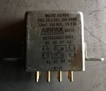
K1 relay is within spec (300 ohms, +/- 30) across the coil (X1 to X2), and there is continuity only between B2 and B3, and A2 and A3.
BA0E82BA-7E8F-4A94-A8F8-201EA11F5198.jpeg
Moving on to see what’s happening at the pumps and output.
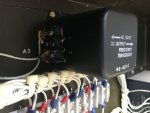
Looking closer at the frequency transducer in the control cubical, the terminals on the AC input side show some melted conformal-ish coating. Does that look normal? There’s a test setup for that item in the I-level TM, but it’s a little beyond me for now, and the frequency meter was working normally during the last test run.
31674824-E451-495C-B377-48E825FDC25F.jpeg
 

Guyfang

Moderator
Staff member
Moderator
15,869
22,091
113
Location
Burgkunstadt, Germany
Easy way to test the freq transducer is to simply hook up 120 volts the the AC side and the hertz meter should read approx 60 hertz. No, what ever that crap is on the terminals is not normal.

The K1 can be tested. Apply 24 VDC to the coil. The test is in the TM. I think I may have writen up an easy way to test. Will look as soon as I can get to my computer.
 

Guyfang

Moderator
Staff member
Moderator
15,869
22,091
113
Location
Burgkunstadt, Germany
The attached scan is about the easiest way to test the K1.

1. Pull out the CB1, DC control circuit breaker. This does not mean there is no DC in the control cube, so do be careful.
2. Remove the wires from terminals 2,7.8 and 9, of the A4 circuit card in the control cube. Move them away, or tape them off.
3. Then attach one wire to ground, and one wire to the Ammeter Shunt. The thing in the right corner of the control cube, that looks, (and is) a fuse able link. It is ALWAYS hot, unless you disconnect the battery's. So do be careful.
4. Then hook the ground wire to terminal A4-8, and the 24 VDC wire to A4-2.
5. You should hear a click. That's the relay working, (you hope). When it clicks, test for ohms on A4-1 and A4-3. You should not get continuity. Test on A4-7 and A4-9, you should get continuity.
6. Remove the hot wire to A4-2, and recheck the A4-7 and A4-9 terminals. You should not have continuity. On terminals A4-1 and A4-3, you should get continuity.

This is a simple in set test. Its in the book.

If you do this kind of thing professionally, get a relay socket, and make a simple tester. I mounted mine on a pound cake C-Ration can. Two test points for my + & - leads. The leads had roach clips on them to attach to a power source. Then I took 5 lights out of an old Fault indicator, and mounted them on the side of the can. The lights were wired to the relay socket to light when the contacts were made and when they were not made. The fifth light was just to tell me I had 24 volts to my rig. I made it one night on 24 hour duty, and used it for the next 20 years. Simple, and handy.
 

Attachments

DJ362

New member
13
24
3
Location
White Salmon, WA
Thanks again! I appreciate the cautions in your write-up.
I’m the furthest thing from a professional, but making the tester will be worthwhile. I will print out the TMs and try to get my head around the controls and relays before doing more tests.
 

Guyfang

Moderator
Staff member
Moderator
15,869
22,091
113
Location
Burgkunstadt, Germany
Unless you do this for a living, the test set is simply a extra. Not needed, but nice. I used mine 10 million times over the years, but this is what I did for 20 years in the army and 8-9 years as a contractor.
 

DJ362

New member
13
24
3
Location
White Salmon, WA
I understand. It’s good to have access to your expertise here.
Following up - the problem went away before I tested further. Which is great but could be temporary to an unknown degree, etc. For now, I’m blaming moisture and I’ll build a generator shed.
Since we first had the problem after a normal shut down, I’m continuing to engage the emergency stop after I shut down. Probably best if I install a master switch for the generator battery.
 
Top
AdBlock Detected

We get it, advertisements are annoying!

Sure, ad-blocking software does a great job at blocking ads, but it also blocks useful features of our website like our supporting vendors. Their ads help keep Steel Soldiers going. Please consider disabling your ad blockers for the site. Thanks!

I've Disabled AdBlock
No Thanks