

jasher33
New member
- 6
- 5
- 3
- Location
- Lebanon, OR
Hello Everyone,
My farming buddy got us into a project we need some advice on. He purchased a MEP 006A the other month relatively cheap but with a very low voltage output. We have looked at A LOT Of material on this site (and the manual) and I finally signed up. I will keep it brief as I am known to talk too much, but below is a list of things we have tried from the manual and various posts. I can provide further detail and pictures if need be, it’s sitting back by my old barn.
The motor runs good, we don’t have a tach, which is unfortunate. When we rev it up to about what I’m guessing is a bit under 2000 RPM (just form sound). At the courtesy outlet plugs I get 10V AC.
I measured Voltage between T1 → T2 T1 → T3 T2 → T3 Those readings all said 20v AC. Between T1 → T10,T11,T12 it was around 11 volts, The same for the rest.
What we have done with the voltage regulator →
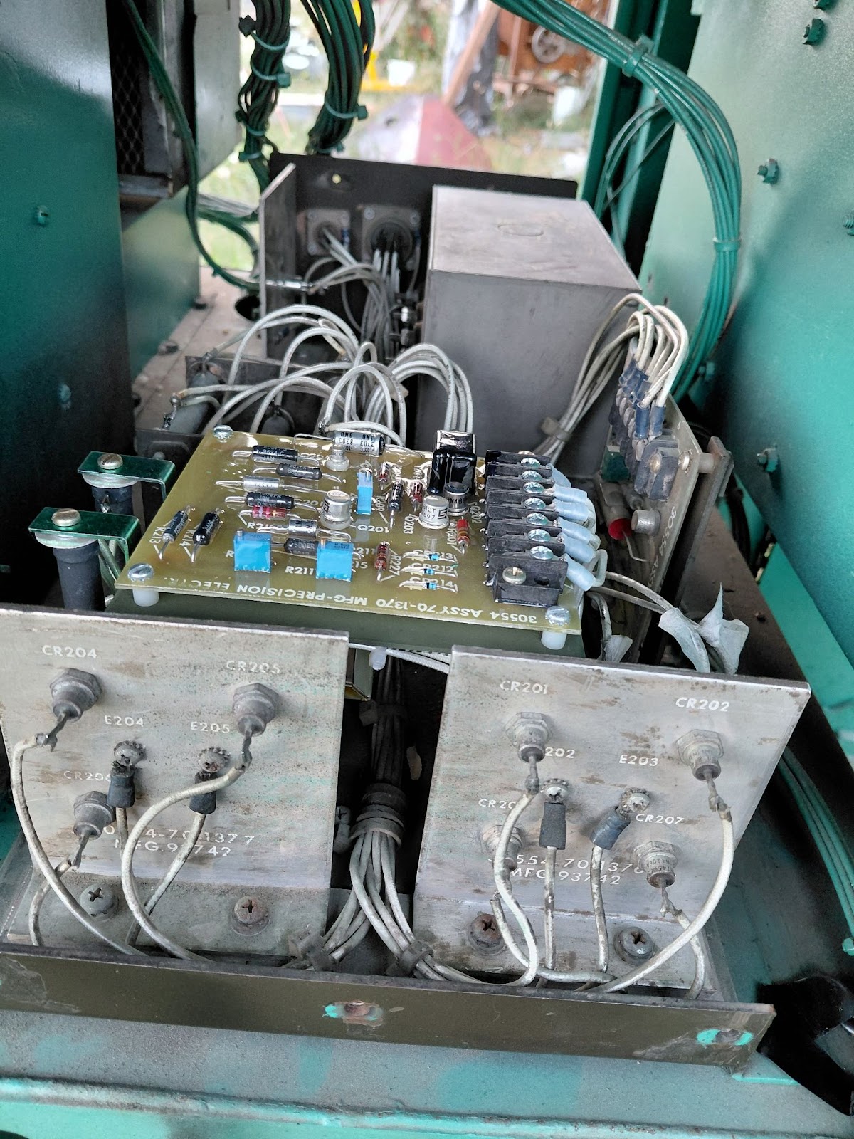
Replaced the voltage regulator board and transformer with new old stock from eBay. I originally ran the test using the Variac and DC Power supply. I was seeing next to no voltage on the 100ohm 25watt resistor I put on lines S and T. That is why we went ahead and got a new regulator board. After installing that board I did get volage that did drop to almost zero when I increased the AC towards 90. It was not what the manual said it would be, it was about 16V not the 25 or 30 that the manual wanted. Concerning still.
I also ran the test on the Electronic Assembly board, ended up frying the full wave diodes on that but I have replaced them since. I also replaced SCR (Q205).. The RFI module looks to have been replaced at some point, it tested out correctly. I tested the rectifier in the assembly and they all had a normal forward bias of around 0.5V. The large resistors also tested out to their specifications.
We decided just to give it a shot and re-installed the exciter assembly. Still outputs low voltage.
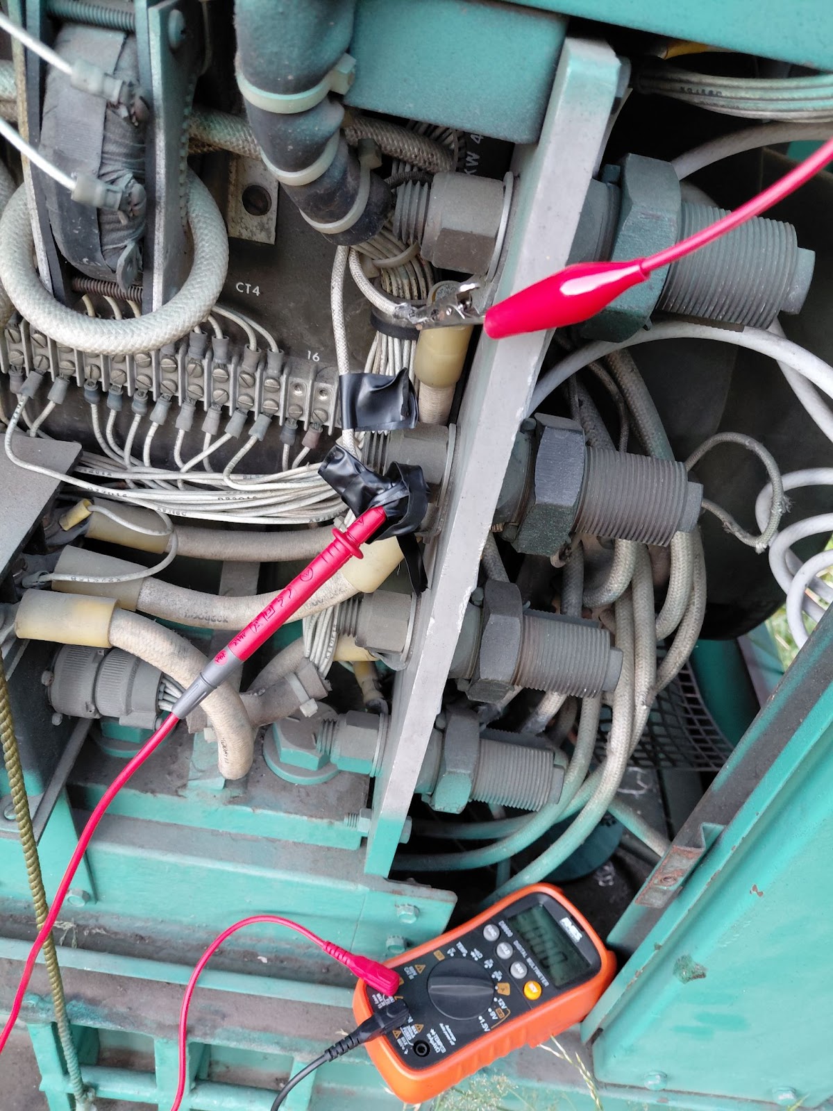
Rectifier Diodes on the Exciter back of Generator →
I tested all of these with a forward-biased test, they all read about 0.43V in one direction and 0L in the other. There was one I was kinda unsure about it flashed the wrong direction on the meter once.
I also attempted to test these according to the manual which references the alternator diode testing and says I should be getting less than 20 Ohms in one direction. I tried this on the back diodes (3 only so far I quit for the night last night). I’m not getting any small ohms resistance. I don’t know if its my meter or Im doing it wrong. I have the diodes unbolted and I'm checking across them. The ohm’s are in the mega ohms and one of the diodes has a measurement in both directions…
Im not sure if Im doing something wrong or not. I am not a professional electrical guy. I know enough to be dangerous. But I worry that I have not approached something correctly….
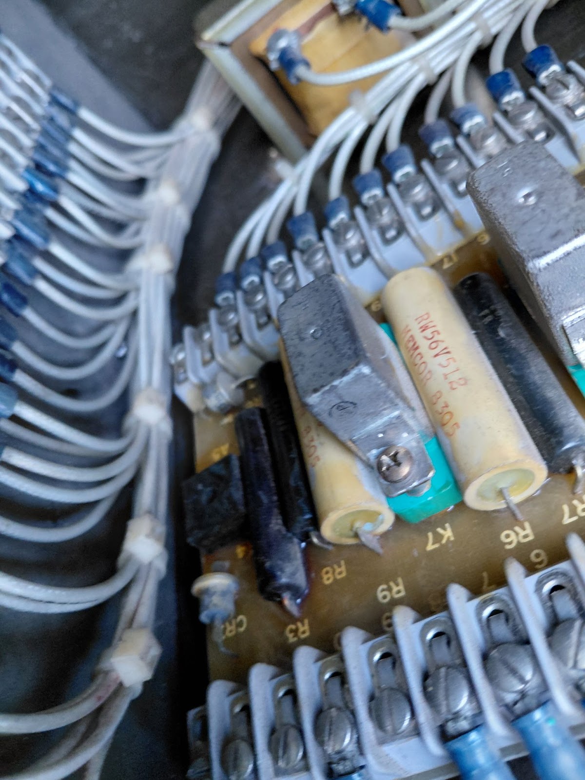
Another note: We tried to bypass K5 and flash the field if that matters, relay seems to click and we believe the speed switch is working. NOT 100% will not lie but we did try and poke at that. There are some components on the bottom of that board (part of the overload circuit?) that look like they got pretty damn hot. I don't have a picture, but the back of the board behind that big resistor is browned.
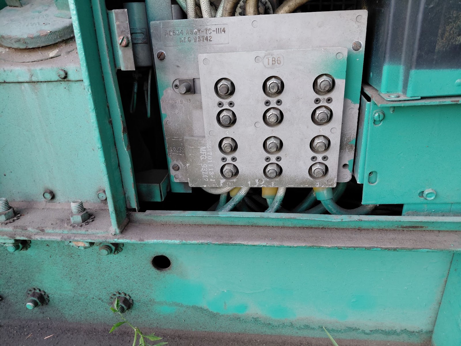
Testing at TB16 Terminals 15 and 16
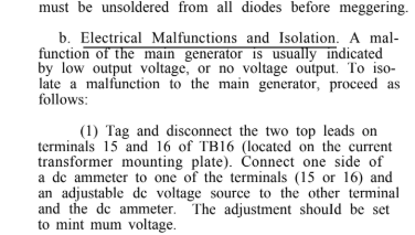
This test we did last night, and at this point, is kinda why I'm reaching out for help. I hooked up the test setup as mentioned in the instructions. Started the generator, brought it up to what I think is around 1800 RPM (and then increased it anyways). Then brought the DC power supply slowly up, I went up to 24V. It looks like it should only need 4? Regardless, I never got any current draw when the ammeter, power supply, and terminals 15 and 16 were connected in a circuit. They said I could use either terminal so I only hooked it up in one direction. Dont know if that matters…. I am assuming those two lines feed into the exciter? And those are normally connected to the output of the excite assembly/voltage regulator? II tested voltage between the other terminals connected to 15 and 16 on TB16, and I didn't get anything either. The lines going into the generator (excite lines?) I measured 3 ohms.
Im really just wondering where I might have gone wrong or where to go next if anyone has any advice. I hope I dove deep enough here to provide good information I was trying to before I posted for any help.
My farming buddy got us into a project we need some advice on. He purchased a MEP 006A the other month relatively cheap but with a very low voltage output. We have looked at A LOT Of material on this site (and the manual) and I finally signed up. I will keep it brief as I am known to talk too much, but below is a list of things we have tried from the manual and various posts. I can provide further detail and pictures if need be, it’s sitting back by my old barn.
The motor runs good, we don’t have a tach, which is unfortunate. When we rev it up to about what I’m guessing is a bit under 2000 RPM (just form sound). At the courtesy outlet plugs I get 10V AC.
I measured Voltage between T1 → T2 T1 → T3 T2 → T3 Those readings all said 20v AC. Between T1 → T10,T11,T12 it was around 11 volts, The same for the rest.
What we have done with the voltage regulator →
Replaced the voltage regulator board and transformer with new old stock from eBay. I originally ran the test using the Variac and DC Power supply. I was seeing next to no voltage on the 100ohm 25watt resistor I put on lines S and T. That is why we went ahead and got a new regulator board. After installing that board I did get volage that did drop to almost zero when I increased the AC towards 90. It was not what the manual said it would be, it was about 16V not the 25 or 30 that the manual wanted. Concerning still.
I also ran the test on the Electronic Assembly board, ended up frying the full wave diodes on that but I have replaced them since. I also replaced SCR (Q205).. The RFI module looks to have been replaced at some point, it tested out correctly. I tested the rectifier in the assembly and they all had a normal forward bias of around 0.5V. The large resistors also tested out to their specifications.
We decided just to give it a shot and re-installed the exciter assembly. Still outputs low voltage.
Rectifier Diodes on the Exciter back of Generator →
I tested all of these with a forward-biased test, they all read about 0.43V in one direction and 0L in the other. There was one I was kinda unsure about it flashed the wrong direction on the meter once.
I also attempted to test these according to the manual which references the alternator diode testing and says I should be getting less than 20 Ohms in one direction. I tried this on the back diodes (3 only so far I quit for the night last night). I’m not getting any small ohms resistance. I don’t know if its my meter or Im doing it wrong. I have the diodes unbolted and I'm checking across them. The ohm’s are in the mega ohms and one of the diodes has a measurement in both directions…
Im not sure if Im doing something wrong or not. I am not a professional electrical guy. I know enough to be dangerous. But I worry that I have not approached something correctly….
Another note: We tried to bypass K5 and flash the field if that matters, relay seems to click and we believe the speed switch is working. NOT 100% will not lie but we did try and poke at that. There are some components on the bottom of that board (part of the overload circuit?) that look like they got pretty damn hot. I don't have a picture, but the back of the board behind that big resistor is browned.
Testing at TB16 Terminals 15 and 16
This test we did last night, and at this point, is kinda why I'm reaching out for help. I hooked up the test setup as mentioned in the instructions. Started the generator, brought it up to what I think is around 1800 RPM (and then increased it anyways). Then brought the DC power supply slowly up, I went up to 24V. It looks like it should only need 4? Regardless, I never got any current draw when the ammeter, power supply, and terminals 15 and 16 were connected in a circuit. They said I could use either terminal so I only hooked it up in one direction. Dont know if that matters…. I am assuming those two lines feed into the exciter? And those are normally connected to the output of the excite assembly/voltage regulator? II tested voltage between the other terminals connected to 15 and 16 on TB16, and I didn't get anything either. The lines going into the generator (excite lines?) I measured 3 ohms.
Im really just wondering where I might have gone wrong or where to go next if anyone has any advice. I hope I dove deep enough here to provide good information I was trying to before I posted for any help.


")


