• Steel Soldiers now has a few new forums, read more about it at: New Munitions Forums!

  • Microsoft MSN, Live, Hotmail, Outlook email users may not be receiving emails. We are working to resolve this issue. Please add support@steelsoldiers.com to your trusted contacts.


MEP-006a - no power/no engine start issue

Guyfang

Moderator
Staff member
Moderator
15,826
21,986
113
Location
Burgkunstadt, Germany
If you have a soldering iron, remelt the trace. Sometimes it helps. If not, put the A4 back on the wall. Then take the K1 relay out. Spin it 180 degrees, and put it back in. Then test the A4 again for continuity on A4-7 and A4-9. Sometimes only one set of contacts stop working on these relays. If it still doesn't work, then we will do this. If you have a spare K1 relay, simply plug it in and test the A4. If you do not have a spare K1, we will do some "field" repairs.

Remove the Fault indicator. Take the 5 screws out on the left side of the indicator, pull the plate out. There before your eyes should be a relay, screwed to a circuit board. Remove it, and plug it in on the A4 board in the K1 socket. Then test your A4 card. This should fix it. If so, then you need a relay for your fault indicator, but that's not such a big thing. The set runs just fine without the indicator. But it sure helps you figure out why the darn thing stops in the middle of the night.

The relay is to be found in the internet. There are some that have a price about the same as the GDP of Uganda. If you look hard enough in the net, you can find cheap one. If you need help finding one, I have the time.

I should thank you for giving me something to do.
 

fpac

New member
20
0
1
Location
Bedford, IN
Still stuck on the A4 issue. I reheated the solder and smoothed it up some and rechecked continuity on the back of A4...still have it. No change on the front side with continuity between A4-7 and A4-9 or change in voltage to A4-9. Pulled the relay out of the fault indicator box, appears to be new. No luck there either, flipping around etc. Is there a test for the relays...say for example, apply voltage to pin 1 and measure continuity on another couple of pins??

Reading through all of your posts, I went back to R13. About took 10 steps backward in this process. Learned really quick that CB1 doesn't cut power to the entire box. Hit the wrong spot on it and sparks when flying...lost all power for a bit. Started checking and rechecking, tracing the path as you laid out....not sure what happened but everything is back on track. Is it possible for the relays to reset themselves?

The reason I went back to R13 was you'd mentioned running the jumper from the positive terminal to A4-9. What I've found is both nuts on the "front" and the two screws on the top are all "hot". The only thing that doesn't illuminate my test light are the two screws holding it to the side of the box. Is this correct? Looking at the schematic, power seems to be going away from R13? At least that is how I read the arrows. I know it has to have power coming in somehow, but this is another spot when it comes to reading the schematic that messes my thought process up.
 

Guyfang

Moderator
Staff member
Moderator
15,826
21,986
113
Location
Burgkunstadt, Germany
Still stuck on the A4 issue. I reheated the solder and smoothed it up some and rechecked continuity on the back of A4...still have it. No change on the front side with continuity between A4-7 and A4-9 or change in voltage to A4-9. Pulled the relay out of the fault indicator box, appears to be new. No luck there either, flipping around etc. Is there a test for the relays...say for example, apply voltage to pin 1 and measure continuity on another couple of pins??

Yes. Here is how you can do it, and check out the A4 card.

Remove all wires from the A4. Don't mark them. Just remove them.

Then pull the A4 out of the control panel. Take it around to the right side of the set. Connect a wire from ground to A4-2. Take a wire and go from the positive side of the starter, and let it hang down.

Get your multi meter and test for ohms between A4-1 and A4-3. You should get continuity. Then measure for ohms between A4-7 and A4-9. You should get nothing. Then take the positive wire hanging down, and connect it to A4-8. You should hear a click. Check between A4-1 and A4-3. You should get nothing. Check between A4-7 and A4-9. You should get continuity. If all this happens, then K1 is good, and the K1 circuits on the A4 card are good.


Reading through all of your posts, I went back to R13. About took 10 steps backward in this process. Learned really quick that CB1 doesn't cut power to the entire box. Hit the wrong spot on it and sparks when flying...lost all power for a bit.

Popping the CB1, should cut off most power to the control panel. Look at page 62. Find the CB1 in the upper left hand side. copy the wire number, and positions. All that's important is that P141D and P141D are on one side of the switch, and P40NA is on the other side. Measure from ground to the one wire, (P40NA), you should get 24VDC. Then measure from ground to the two other wires, should get 24VDC. Pop the CB1, and there should not be 24VDC on the one wire. Some times the CB1 is hooked up wrong, or will not open its contacts.

Started checking and rechecking, tracing the path as you laid out....not sure what happened but everything is back on track. Is it possible for the relays to reset themselves? (Relays do not reset themselves. Or better said, some do, but none in this set. )

The reason I went back to R13 was you'd mentioned running the jumper from the positive terminal to A4-9. What I've found is both nuts on the "front" and the two screws on the top are all "hot". The only thing that doesn't illuminate my test light are the two screws holding it to the side of the box. Is this correct? (Yes it is correct) Looking at the schematic, power seems to be going away from R13? At least that is how I read the arrows. (the arrows indicate how the cannon plugs are set up. The point of the arrow is a pin, the other side of the arrow is the socket) I know it has to have power coming in somehow, but this is another spot when it comes to reading the schematic that messes my thought process up.

Think of R13 as a fuse-able link. The battery system has enough amps that you can weld with it. You do not want that kind of amperage in the control panel, where you could burn up things. So the R13 has a real thin middle link. Take a look. If you get a short, in the control panel, the link melts before enough amperage to burn a wrench in half, can do major damage. It also keeps the battery charging meter from having mega amps on the two terminals on the back of the meter. Power comes in on terminal 1, or the R13.

A4 wires

1. empty
2. P55mm
3. empty
4. X31A
5. X12G
6. X79A
7. P45E
8. P80E
9. P50A
10. X78A
11. X82B
12. X29A

I never mark wires, always check them before rehooking them. One misplaced wire can screw you up for ever.
 

fpac

New member
20
0
1
Location
Bedford, IN
Testing A4 and relays as spelled out, they work, but still not able to get fuel pumps or starter to engage.

Checked out CB1 as well and it's working as it should.

Thanks for setting me straight on the plug/receptacle (arrows). I should have easily grasped that seeing the plug ID there as well.
 

Guyfang

Moderator
Staff member
Moderator
15,826
21,986
113
Location
Burgkunstadt, Germany
OK, the A4 and relays worked right when tested out of the set? Then we need to see why the K1 will not work. Put A4 back into the set. Try and turn on the pumps with the set in the run position. Test A4-2. Do you have 24 VDC? If not, then turn S7 on. Do you have 24 VDC at A4-2?

Another question. Do your panel lights work? turn them on and see.

In the control panel, do you have 24 VDC at TB1-3 and TB1-4 when you try and turn on the pumps?
 
Last edited:

fpac

New member
20
0
1
Location
Bedford, IN
Correct, the A4 and relays worked when testing out of the set.

No 24 VDC at A4-2 with S2 at Run. No 24 VDC at A4-2 when S7 is on. And no 24 VDC at TB1-3 or TB1-4 with S7 set to run the pumps.

The panel lights do work.
 

fpac

New member
20
0
1
Location
Bedford, IN
Let's see if I can do this without much confusion.

S2 - off position -- 24VDC at S2-2, 5, and 11
S2 - on position -- 24VDC at S2-2, 5, 11, and 3 (have 24VDC at S2-6 when S7 is on)
S2 - start position -- 24VDC at S2- 2, 5, 11, as well as 3, 6, and 12 (no 24VDC at S2-12 when S7 is on)

S7 - off position -- S7-7, 8, 10, and 11 have 24VDC
S7 - on position -- S7-7, 8, 9, and 12 have 24VDC


Moving out from S2.
I have 24VDC to A4-7, but not to A4-9. I get 24VDC to TB101-11...tracing the P45.
I can also get 24VDC to A5-16 and A5-4 when S2 is set to start. However, I cannot get 24VDC to TB101-9 which makes no sense...based on page 62. I've not had time to trace it yet.
 

fpac

New member
20
0
1
Location
Bedford, IN
I rechecked TB101-9 and this time was able to get 24VDC....must have not had a good ground or couldn't count correctly earlier....

Tracing voltage from A5-4 to P53A at the Oil Pressure switch I have 24VDC. If my thought process is correct....the engine is not running and not producing oil pressure so the switch is open so I cannot get voltage to wire P58?? Rearranging plug wires (somebody had put in spade connectors) and using P200 and P201 for the fault indicator side of the switch routing 24VDC through the OP switch to P58. With this method I was curious and flipped S7 on and the fuel pumps ran. Turning S7 off and pushing S2 to start I could also get the fuel pumps to run, but the engine did not crank.
 

Guyfang

Moderator
Staff member
Moderator
15,826
21,986
113
Location
Burgkunstadt, Germany
I think you need to relook the plugs and the wires. What plugs were cut off and replaced? Is there any other place that the wire harness was cut/repaired?
 

fpac

New member
20
0
1
Location
Bedford, IN
Various wires have been repaired. So far, those that I have checked have been good for continuity.

Some known issues I've found along the way, prior to really digging into this recently, is that S1 ,ether kit, doesn't function. I have found continuity all the way through. I also know that DS6 needs replaced. My assumption is that neither were critical to starting the unit.

Any more thoughts on A4-7 and A4-9 not functioning? Possible A4 still has a problem?

Thanks for your input!
 

Guyfang

Moderator
Staff member
Moderator
15,826
21,986
113
Location
Burgkunstadt, Germany
This is not an A4 card problem. K1 is not getting 24 VDC to the input side of the coil. I ned to think about your post #30, and maybe you need to not just check continuity, but test to make sure the right wire is connected to the right pin. Tell me what harness and or plug was cut off.
 

fpac

New member
20
0
1
Location
Bedford, IN
I don't think any of the big cannon plugs were cut off. The plugs that have been reworked for some reason are for the oil pressure and water temperature safety switches. I've checked the wire labels and make sure they match the A,B,C,D of the plugs. Checking those for continuity and VDC, they've checked out.

I have found splices in wires such as P199 in the control panel which goes to DS6. Wires X12A and K32B in the loom running from cannon plug J1 to J2 have been spliced. I've not made time to look for the schematic covering those. I've not found those wires listed on page 62, so far. There is a wire going into the exciter box through J9 that has been spliced into. There isn't any labeling on it...new wire was used.

The other ends I've found replaced (my assumption) are the newer appearing red wire ends/eyelets attaching to the TB101, TB102, TB1 type boards. The original wire ends/eyelets appear to be white.
 

Guyfang

Moderator
Staff member
Moderator
15,826
21,986
113
Location
Burgkunstadt, Germany
For this kind of work, the -34 manual is perhaps best. All the connections, terminals and such are in one place along with wire numbers.For instance on PDF reader page #53, is the special relay box laid out, so you can see what wire goes from what plug to what place. Every interconnecting wire harness is listed in the -34 TM also. You can track a wire from start to finish. This was the bible when we had wire harnesses badly damaged.
 

Guyfang

Moderator
Staff member
Moderator
15,826
21,986
113
Location
Burgkunstadt, Germany
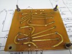
Can you take the A4 card off the control panel wall and make a picture of the back side? An old friend of mine just wrote me that the A4 should have a diode soldered to the back side of the card, and its NOT in the schematic. I do not remember this, but the last time I worked on one of these things was 2000? Or maybe even longer.
 

fpac

New member
20
0
1
Location
Bedford, IN
There is a picture of A4 in post 18. If you need a close up of a certain spot, I can certainly take it off and get another picture.

I found a picture of another A4 on a vendor's page and it appears to be the same design.
 

fpac

New member
20
0
1
Location
Bedford, IN
I do see that A4-9 has arc'd at some point.

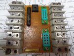
A4 terminal board - front.JPG

Took another picture of the back. May allow you to see it a little better than the picture in post 18. As mentioned earlier, somebody had touched up the back for one reason or another. I re-streaked it with my soldering iron as you suggested. It had continuity before and after I used the soldering iron.

A4 terminal board - back.JPG
 
Top
AdBlock Detected

We get it, advertisements are annoying!

Sure, ad-blocking software does a great job at blocking ads, but it also blocks useful features of our website like our supporting vendors. Their ads help keep Steel Soldiers going. Please consider disabling your ad blockers for the site. Thanks!

I've Disabled AdBlock
No Thanks