• Steel Soldiers now has a few new forums, read more about it at: New Munitions Forums!

  • Microsoft MSN, Live, Hotmail, Outlook email users may not be receiving emails. We are working to resolve this issue. Please add support@steelsoldiers.com to your trusted contacts.


MEP-016B Voltage Selecotr

kmapatriot

New member
7
0
1
Location
Ponca City, OK
I can't quite figure out what the voltage selector settings mean on V1-0, V2-0, V3-0, V1-2, V2-3, and V3-1.

For 120V 1 phase and 120V three phase, where do I need to set them at?

Mark
 

ETN550

New member
457
9
0
Location
Knoxville, TN
Hi I've had as few of the 016B's and hope to have a few more in the future. They are very nice units.

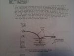
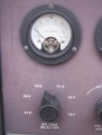
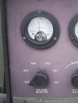
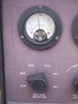
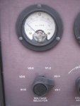
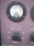
The voltage selector switch chooses which two leads are sent to the panel voltage gage for a reading. The position of the voltage selector switch tells the voltage gage what to read. It is okay to move the switch during operation and nothing is affected operationally.

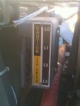
The 0, 1, 2, 3 on the switch refer to the L0, L1, L2, and L3 on the output block on the back of the contorl box.

For example: you are set in 120 volt single phase mode and have the output hooked up to L1 and L2. Set the switch at V1-2 and it will give you a reading, of the voltage between L1 and L2, hopefully 120 volts.

In 240 volt single phase mode your output is still connected to L1 and L2 but now when the voltage selector switch is moved to V1-2 it will read 240 volts. If you are in the 240 volt single phase mode and move the voltage switch to V1-0, or V2-0 the gage wil read 120 volts which is the voltage between L0 and L1 and also the voltage between L0 and L2.

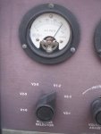
Same concept in 3 phase mode. Bottom line, by using the voltage selection switch you can see the voltage accross all the combinations of output wirs with only using one gage on the panel. Nice feature on a small gen, really.

When you do a start up and before a load is applied moving the voltage switch to each position will confirm that the selection switch inside the box is set the way you want it for your use.

So to answer your question: For 120 single phase set the voltage switch at V1-2. For 120 three phase the switch can be moved around from V0-1 to check the voltage between L1 and L0 to V0-2 to check the voltage between L2 and L0 and to V0-3 to check the voltage between L3 and L0. All three are active in the three pahse mode and the switch must be moved around to get a separate reading for each pair. Since 3 phase is three separate circuits there may be small differences in the voltage on each line due to load variances if there is different equipment connected to each of the three phase lines. If a three phase device is connected like a 3 phase motor than the voltages would be the same.

Equally useful is the current selector switch that lets one see how much load is on each of the putput lines, L1, L2, L3. when running three phase with 3 separate loads it is useful to balance the loads so I1, I2, and I3 are as equal as possible.
 
Last edited:

kmapatriot

New member
7
0
1
Location
Ponca City, OK
Thank you for the input, that most certainly makes more sense now. This is my first experience with trying to run one of these generators. I bought it off Gov't auction.

Actually made some headway on getting things figured out. Don't quite understand the -12 manual tho,
the actual load connections are in a different order from mine.

I did check voltage, looks like it was at 105.7 volts. Is that about right?
 

Attachments

ETN550

New member
457
9
0
Location
Knoxville, TN
Thank you for the input, that most certainly makes more sense now. This is my first experience with trying to run one of these generators. I bought it off Gov't auction.

Actually made some headway on getting things figured out. Don't quite understand the -12 manual tho,
the actual load connections are in a different order from mine.

I did check voltage, looks like it was at 105.7 volts. Is that about right?
Correct, the manual has problems with the grounding instructions and the labeling on the winding diagrams. There are some other posts on this site addressing that issue.

My guess is that there were modifications made along the way to allow the L0 to be grounded and let the machine make 120 / 240 at the same time. It was originally designed to only make 240 in the single phase 240 mode. I do speculate that the grounding modification applied might have something to do with a later modification that made a change but I never got any definitive answer. Sure would be great to find someone who worked on these sets for a living in the military.

Do this test to confirm. Put the reconnection switch inside the control box to the 240 single phase setting. Run the machine with nothing connected. Measure L1 - L2 with a meter to confirm 208 to 240 volts output. Measure L0 - L1 and L0 - L2. Each should be half of the L1 - L2 reading. If so then always ground L0 when running in the 240 single phase mode. Note that when 120 single phase is selected the ground has to be moved to the L2 as in the manual. Actually for 120 single phase mode either L2 or L1 can be used as the ground. (But not L0)

What mode were you in and what terminals did you measure to get the 105.7 reading? Use the voltage adjust knob to raise or lower the voltage. As a rule the set is designed to allow voltage adjustment to be between 208 and 240 volts when runningin the 240 single phase mode. If it can get near those numbers by moving the knob full travel than it is in good shape, no issues.

A simple rule to remember is always ground L0 except in 120 single phase when L2 is grounded.

Doug
 
Last edited:

kmapatriot

New member
7
0
1
Location
Ponca City, OK
Thank you Doug!

That was most certainly helpful figuring out what's going where!

240 1 Phase
L1-L2 = 240.1 (used voltage adjustment to get it 240.1 plus/minus on hand held meter)
L0-L1 = 120 (on hand held meter)
L0-L2 = 120 (on hand held meter)

Voltage Selector
V1-0 = 110
V2-0 = 110
V3-0 = 0
V1-2 = 220 (first line past 200)
V2-3 = 0
V3-1 = 110
 

Attachments

ETN550

New member
457
9
0
Location
Knoxville, TN
Thank you Doug!

That was most certainly helpful figuring out what's going where!

240 1 Phase
L1-L2 = 240.1 (used voltage adjustment to get it 240.1 plus/minus on hand held meter)
L0-L1 = 120 (on hand held meter)
L0-L2 = 120 (on hand held meter)

Voltage Selector
V1-0 = 110
V2-0 = 110
V3-0 = 0
V1-2 = 220 (first line past 200)
V2-3 = 0
V3-1 = 110

All looks good!
 

ETN550

New member
457
9
0
Location
Knoxville, TN
Your very welcome. The folks on this board have been very helpful to me too. This is proving to be a very fun hobby for me. I enjoy working on such high quality equipment.

It looks like I'm getting a couple more 016B's one with the Onan that I am familiar with and one with the Yanmar conversion. can't wait to get them home to check them over.

Doug
 
Top
AdBlock Detected

We get it, advertisements are annoying!

Sure, ad-blocking software does a great job at blocking ads, but it also blocks useful features of our website like our supporting vendors. Their ads help keep Steel Soldiers going. Please consider disabling your ad blockers for the site. Thanks!

I've Disabled AdBlock
No Thanks