• Steel Soldiers now has a few new forums, read more about it at: New Munitions Forums!

  • Microsoft MSN, Live, Hotmail, Outlook email users may not be receiving emails. We are working to resolve this issue. Please add support@steelsoldiers.com to your trusted contacts.


MEP-017a - No Output, What to do next?

tsdp

New member
5
0
0
Location
henderson, ky
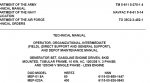
Over the past couple weeks, I have been trying to get my recently purchased MEP-017 to "generate".

I have read the manual, read posts on this forum, purchased a new voltage regulator, and have many hours invested.

The voltage output is low (30 - 50 volts), the hz meter reads low and does not raise if I throttle up the engine. Both voltage and hz meters work fine on 120 VAC house current.

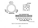
The field flash circuit works, exciter field resistance in withing spec. Continuity is complete everywhere I check it., the 3 diodes are good.

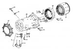
Today, I took everything apart to inspect and check the rotor resistance. The book says the rotor winding to rotor frame should be 8.8 ohms +- 5%. This spec is off just a bit., I am getting about 9.8 ohms with a couple different meters.

I am thing about running the generator with the voltage regulator powered up by 120VAC house current. just to see what happens.

So far, I am defeated by this generator, help me if you can.

Thank You, Trent
 

cranetruck

Moderator
Super Moderator
Steel Soldiers Supporter
10,350
74
48
Location
Meadows of Dan, Virginia
Do you have the TM that shows the generator head wiring? For the mep018 it's as shown below and the individual coils can be checked for continuity.
I burned up the head on mine by running an unbalanced load for a period of time. It may have happened to yours too. The windings are accessible at connector (item #6 in the second image below).
Never run the engine at idle. Should always be 3600 rpm.
 

Attachments

Last edited:

derf

Member
926
13
18
Location
LA
Before I insert household current into anything I'd try a little DC on the Field and see if you get any AC out of the stator. There should be procedures for checking the VR in the TMs. Is the VR putting out DC to the Field when it is running?
It might use the same VR as the 016s.
Also, sometimes diodes check out fine at rest and then fail when loaded..
 

derf

Member
926
13
18
Location
LA
You are running it at 3600RPM, right? Anything not close to 3600 and all bets are off, it will do all sorts of crazy things if turning way too slow or way too fast. I wouldn't worry about way too fast but slow can certainly be an issue.


tsdp

New member
5
0
0
Location
henderson, ky
Thank You for the replys. Cranetruck, My windings read .2 - .3 ohms. I have 2 generator heads, and they are both read the same.

Derf, I have applied up to 30 vdc to the field. AC output will go up as high as 50 volts. When I remove the DC, the AC drifts down.

To test the control box, connections, and big reconnect switch, I put 120VAC into connection (with gen head and VR UNHOOKED) where gen head connects. Doing this allowed me to to pass a load through the box. All went well, ran the shop vac, voltage meter and hz meter work well. To me this proves no bad connections along the 120 V paths.

3600 RPM? I do not know... How can I test engine speed?

I don't want to give up. I want to at least know for sure what has failed.

Thanks, Trent
 

derf

Member
926
13
18
Location
LA
Most Briggs and Tecumseh generators and lawn mowers run at 3600RPM WOT. If you gen seems to be running about the same speed as a lawn motor motor at wide open throttle then you are probably in the neighborhood. You might run the gen with your 30VDC into the field, getting 50 or 60 VAC out and read the frequency of the AC out. If the gen is running at 3600RPM then the output frequency should be 60Hz. If you get 30Hz or something you might look at your engine speed. Is it purring along or screaming like a banshee? I think they lean toward banshee when running properly.


Isaac-1

Well-known member
1,970
48
48
Location
SW, Louisiana
You may have a burned out winding, but my gut feeling here tells me you have a bad diode. You should be getting a lot more more than 50V AC when feeding in 30V DC to the exciter with the VR disconnected. Anyway diodes are just a few dollars to try, if the winding is shot then it is likely not worth fixing given how cheap running ones (or nearly running ones) sell for.

Ike
 

tsdp

New member
5
0
0
Location
henderson, ky
Actually, I have 2 generators, and I am using what I have to get one going. So far, I have changed out the complete rotor assembly (first one had new diodes). Same results after changing rotor. I hope the diodes don't fool me, I have checked them by passing a couple amps at 12 volts through them. I have a total of 9 diodes, they are not shorted. Today, I will read the book about the diode testing details again (I think it gives specifics) After I feel good about the diodes again, I will change out the entire outer housing. How common is it to loose windings? With over current protection, and cooling like it has how can if fail? Do the windings age and cause a failure? This thing looks really tough, all windings I can see look good. It drives me crazy not to be able to fix something.

Thanks again.
Trent
 

derf

Member
926
13
18
Location
LA
Windings are usually good or not. If they read within spec they are almost always good. If you end up with an extra gen head let me know. I want a 017 head for a project.

To check diodes you must remove them from the circuit, i.e. disconnect one end or the other or both. Then, put the meter on the diode symbol (looks kinda like an arrow and a plus sign combined). Read with black lead on one end and red lead on the other. Reverse the leads and read again. You should get something (my Fluke meters generally show .435 or so but that can vary with meters) in one direction and nothing in the other direction. Diodes can either open or short. Open will read nothing in both directions and short will read 000 in both directions. The key is to remove them from the circuit. If your meter does not have a diode symbol then you can use Ohms (Omega symbol) but the readings will be similar but not quite as straight forward.
Did you remove the diodes from the circuit to test them? Remember you only have to remove one end to effectively remove it from the circuit.


tsdp

New member
5
0
0
Location
henderson, ky
Solved…
I finally found the problem, everything works fine now. Today’s troubleshooting started with unhooking P2, supplying 12VDC to F1 and F2, then looking for AC voltage on T2 and T5. This completely bypassed the control box, and proved that the generator was OK.

Next, I went to find the open connection in the box. Every connection through the re-connect switch was fine. Connections feeding the VR were fine, Connections from VR 5 and 6 to relay panel A 15 and 16 were fine. Connections from relay panel A 15 and 16 to J2 were NOT GOOD. Broken field wires at J2 was the problem. The J2 jack is pretty hard to access, but I was able to solder new wires onto it.

Assuming something serious wrong, got me. Simple and COMPLETE continuity tests wounld have saved me some time and frustration.

Thanks again, Trent
 
Top
AdBlock Detected

We get it, advertisements are annoying!

Sure, ad-blocking software does a great job at blocking ads, but it also blocks useful features of our website like our supporting vendors. Their ads help keep Steel Soldiers going. Please consider disabling your ad blockers for the site. Thanks!

I've Disabled AdBlock
No Thanks