cscott719
New member
- 8
- 5
- 3
- Location
- Denver, CO
Hi.
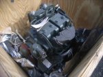
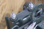
I picked up a DN2M engine that is used in the 802a TQG. The question I have is regarding the heater plugs in the air intake manifold. According to the wiring diagram, these plugs are wired in series. However, I don't know how that would work, because the plug simply has a single screw terminal on top of each one. If there were 2 terminals, that would make sense.
I suspect the plug is grounded through it's body to the intake manifold. If this is true, and a wire is placed under the screw terminal lug from one plug to the other, and then connected to the heater relay, that would effectively put the plugs in parallel, not series as the diagram in TM9-6115-641-24 would suggest.
Does anybody have any insight on this? Perhaps a photo or two showing the wiring? Is it possible that the TM is incorrect? If the plugs are indeed wired in series, and one of them failed, it would prevent the other from working too. In my mind, a series setup would be illogical, because in case of a failure of one plug, the engine would be nearly impossible to start in cold weather. In a parallel wiring, one plug failing would not prevent the other from operating, thus "possibly" allowing the engine to start, since there would be at least some heat applied to the intake.
Thanks!
Scott


