• Steel Soldiers now has a few new forums, read more about it at: New Munitions Forums!

  • Microsoft MSN, Live, Hotmail, Outlook email users may not be receiving emails. We are working to resolve this issue. Please add support@steelsoldiers.com to your trusted contacts.

MEP-802a rotor removal

serial14

Member
101
11
18
Location
Albuquerque, NM
I've spent several days trying all sorts of tactics with out success. This latest attempt had the rotor standing vertical in the air so that the fly wheel was horizontal. We then flooded the problem joint with 50/50 acetone & ATF for several days. Threaded in a bolt in the end of the rotor and lifted so the engine block, skid, and random tools where hanging off the problem joint. Still... no luck.

At this point, I'm thinking of tearing down my other MEP802 which has a bad engine just to see if I can get that one to separate.
 

Guyfang

Moderator
Staff member
Moderator
15,979
22,368
113
Location
Burgkunstadt, Germany
There are several that I can think of, that applied right, would do the job. About the only thing that would weaken them is heat. Or maybe cold? Shoot some CO2 in the plate, then apply the BFH?

But I must admit, this is the ****edest thing I have ever heard of. I was beginning to wonder if you would ever come back up on line.
 

serial14

Member
101
11
18
Location
Albuquerque, NM
the most common suggestion amongst my co-workers is a tie between explosives and a 5-ton tug of war approach. I must admit, that if I'm stumped by the 2nd set these suggestions will get pretty appealing.

I should have more to report this coming week. Several of my brothers will be in town, so I figured I'd put them to work helping me tear down teh 2nd one, and with luck building up a "golden" one.
 

serial14

Member
101
11
18
Location
Albuquerque, NM
Well.... a brother and a niece helped me tear down my 2nd 802 set. Sadly, same problem/issue. I haven't beat on it as much yet, but I've exhausted all "normal" means of separating the two. This one has a black painted adapter plate with white lettered part numbers. So... its obviously a different batch/build from the first one. Same problem though.

Any final advise before something crazy is tried?
 

DieselAddict

Well-known member
Steel Soldiers Supporter
2,486
1,890
113
Location
Efland, NC
I've been curious if there is any way to use a hydraulic pressure solution. As an example used to use grease to remove stuck bearings by putting a shaft into the hole (with grease packed in behind the bearing) then tapping the shaft. The pressure of the grease would push the bearing right out.

Is there any way to seal up the space between the flywheel and plate then use a viscus incompressible fluid to pop it apart?
 

serial14

Member
101
11
18
Location
Albuquerque, NM
Diesel Addict,

That is an interesting idea. Sadly I don't think there is a way to implement it. 1, there isn't a hole in the adapter plate other than the bolt holes. 2, There is a void between the problem adapter plate and the fly wheel, but I don't know how big it is and where it is if I wanted to create a hole.

I've heard of this technique before in relation to bearings, but I've never had the chance to implement it my self before.

Guyfang, you mentioned making it cold with CO2. Can you elaborate on that? Certainly the adapter plate has less thermal mass to it, so instead of heating a giant fly wheel, maybe cooling the "small" adapter plate could help.
 

Guyfang

Moderator
Staff member
Moderator
15,979
22,368
113
Location
Burgkunstadt, Germany
That's What I would try. The adapter plate should react to the cold much faster then heating the flywheel. Maybe an added benefit would be that if there is some sort of adhesive between the two, that it might become brittle. A few blows with the BFH might break it loose. Or the contraction of the plate might break the seal of adhesive. I tell you, having done this job any number of times, I never had a problem like this. Never. We used CO2 at times to remove things, but more often heat. It's worth a shot. In the mean time, I am going to mail someone
I know in CECOM. Ask if this is something new. It's simply crazy.
 

serial14

Member
101
11
18
Location
Albuquerque, NM
I appreciate the help Guyfang in reaching out. I've reached out to all my Army buddies and everybody is as baffled as I am. Its even stranger to have the same problem on two sets that clearly are from different batches. I did buy them in the same auction lot though from the same place... so maybe that unit did something funky?

I think i'm going to give CO2 a try since its about the last thing I haven't tried before we start pulling on it REALLY hard.
 

serial14

Member
101
11
18
Location
Albuquerque, NM
VICTORY!!!!!

While explosives and tug of war were both great ideas and very satisfying entertainment wise I just couldn't get over the risk of potential energy turning into kinetic energy and launching a heavy piece of something to somewhere it shouldn't go. After a few days away from everything up in the mountains, my dad and I evolved several thoughts into a winning idea.

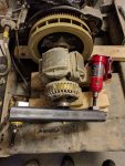
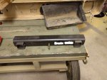
Upfront I'll apologize for not having a complete set of pictures. The excitement and success of our approach had our minds focused on getting both rotors pulled instead of documenting them. However, I think the idea is properly shown in the two pictures.

So we built a "pusher" tool to separate the rotor from the flywheel. The bar is 2"x2"x0.25 with a long Grade 8 3/8" bolt that will thread into the end of the rotor. The two square tubes are just there to help set up the contraption with the proper alignment. 2 4ton bottle jacks are then used as the "pushers". One picture shows the push bar, the other shows an after shot after our first rotor popped loose. You can see the red bottle jack is still mostly in the original place, while a yellow bottle jack has fallen out. 2x4's were stacked to get real close to the rotor so it didn't drop.

In all my previous attempts, I estimate I was able to apply ~400lbs static force, which didn't make it budge. The first rotor we tackled came off pretty easy actually, we "barely" started feeling any force on the jack pumps and it popped off. On the second rotor we pulled( the original one that started this mess ) we had to use significantly more force, I started to see some bow to the 2"x2" steel. I'm not a structural engineer, but its clear that some good amount of force would need to be used to bow a 2x2x0.25 piece of steel over a 13" span. Inspecting the rotor adapter plate and fly wheel did not show any clear reason why they were soo stuck. There was only a couple of very mild & small surface rust spots. No obvious paint bonding, adhesives, etc. So... the root cause remains a mystery.

No its time to start building a working MEP out of the pieces. I already have a NOS engine ready to go, so that should take care of the bulk of the initial problems with these sets. It wasn't my intent to have a super big project on getting a functional MEP, but once I start its hard to give up and admit defeat.

Thank you to all who have suggested ideas and followed along for sympathy.
IMG_20170811_200407.jpgIMG_20170811_200145.jpg
 
Last edited:

serial14

Member
101
11
18
Location
Albuquerque, NM
I've started re-assembling a good generator from all the best parts. The flywheel and rotor assembly I went with was the original one that caused me to start this thread.

I thoroughly cleaned the flywheel and rotor before re-assembly and even used some steel wool to polish some rough spots from the surface rust I found. Re-assembly went smoothly except I noticed that as I was tightening the 5 bolts that whole the two together that right at the end they "clicked" together. In my case, clearly its is a very tight machine fit which is probably why it was soo hard to pull them apart. Hopefully this means that its a very well balanced set and the generator will run smoothly. I anticipate that if I ever had to disassemble this again( I hope not ), that I would have to use my push bar idea again. Its for this potential risk that I'm keeping that bar around for a while before returning it to the scrap metal pile.
 

Ray70

Well-known member
2,394
5,168
113
Location
West greenwich/RI
So can you guys give me the simple procedure to swap out a bad DN2M in an 802A? Is it necessary to dismantle the generator, of can you get inside somehow ( maybe starter hole or through the generator with a very long extension ) to remove the 5 bolts attaching the plate to the flywheel.
Looking at the TM I need to remove the gen end cover, then the long rods ( #18 in pic if I recall ) then I need to unbolt the plate from the flywheel by removing the 5 nuts and bolts. This is where there seemed to be some confusion above, as to whether or not those 5 bolts can be accessed without disassembling the stator and rotor assy.
 

serial14

Member
101
11
18
Location
Albuquerque, NM
Ray70,

From my experience, swapping a motor requires the full tear down of the whole set. For separating the rotor from the fly wheel, you'll need to disassemble the generator section as well. I was only able to get to the 5 bolts with an offset wrench. The spacing is too tight to get a socket & universal joint down in there. I suppose the only thing you don't have to remove strictly speaking is the front section that holds the radiator & fuel tank.
 

Demoh

Member
217
26
18
Location
St Pete, FL
FWIW the 400Hz genhead is much easier to remove and install than the 60Hz unit. I picked up a 400Hz because I needed an engine and the rotor stays in the stator when you pull the 400Hz. You pull an access grill off, disconnect 4x 12point bolts that separate the stator housing and engine, and another 5 or 6 that separates the rotor and fan from the flywheel.

Theoretically replacing a 400Hz engine you wouldnt need to pull the housing off although it would be easier.

Flywheels are different. The fan is on the rotor for the 400Hz unit and the fan is cast into the flywheel on the 60Hz unit. To go further so are the bearings. Not that I would want to ever stock bearings for a 400Hz genhead.

Has anybody successfully changed 60Hz genhead bearings without pulling the stator all the way off? It doesnt look possible but it would be nice to cut down on the labor when I am refurbishing these units. I mean it might be possible with some custom puller.
 

Guyfang

Moderator
Staff member
Moderator
15,979
22,368
113
Location
Burgkunstadt, Germany
So can you guys give me the simple procedure to swap out a bad DN2M in an 802A? Is it necessary to dismantle the generator, of can you get inside somehow ( maybe starter hole or through the generator with a very long extension ) to remove the 5 bolts attaching the plate to the flywheel.
Looking at the TM I need to remove the gen end cover, then the long rods ( #18 in pic if I recall ) then I need to unbolt the plate from the flywheel by removing the 5 nuts and bolts. This is where there seemed to be some confusion above, as to whether or not those 5 bolts can be accessed without disassembling the stator and rotor assy.
No, you can not get at the five bolts without pulling the stator.
 

Guyfang

Moderator
Staff member
Moderator
15,979
22,368
113
Location
Burgkunstadt, Germany
FWIW the 400Hz genhead is much easier to remove and install than the 60Hz unit. I picked up a 400Hz because I needed an engine and the rotor stays in the stator when you pull the 400Hz. You pull an access grill off, disconnect 4x 12point bolts that separate the stator housing and engine, and another 5 or 6 that separates the rotor and fan from the flywheel.

Theoretically replacing a 400Hz engine you wouldnt need to pull the housing off although it would be easier.

Flywheels are different. The fan is on the rotor for the 400Hz unit and the fan is cast into the flywheel on the 60Hz unit. To go further so are the bearings. Not that I would want to ever stock bearings for a 400Hz genhead.

Has anybody successfully changed 60Hz genhead bearings without pulling the stator all the way off? It doesnt look possible but it would be nice to cut down on the labor when I am refurbishing these units. I mean it might be possible with some custom puller.
It is possible to change the bearing without pulling the stator. Look at the -24P.
 
Top