jwhite9787
New member
- 17
- 18
- 3
- Location
- MA
Hi,
I'm going to ask a question that will likely sound uneducated but I can't find a thread that addresses this specifically. Please keep in mind I'm still learning! I'm curious about hooking up a house with a 60 amp connection, which will safely allow for the full capacity of the generator. It seems like most people are satisfied with 50 amp but that seems like you're cutting the generator short of its capabilities. I see people talk about the issue of amperage difference but specifically, I would like to be able to connect 60 amps with a straight blade plug and receptacle. Is this possible? I do see plugs rated at 60 amp however they also say 125/250 volt. Is this an issue? With my little education, I just expect to see single phase plug/receptacles written as 120/240 volt. This voltage difference makes me question if this is still appropriate for home power. I'm guessing it's not an issue as it's simply what the wiring and receptacle/plug are rated to carry. For cable I would be using 50' of 4/4 SOOW. I don't want to go over to pin and sleeve, not for a expense but rather I would like to keep the more common connection so a less powerful generator could still be hooked up later. I plan on setting up an interlock and to do whatever load management might be necessary (likely to be none since I have nat gas utility for heat and some appliances).
I also want to put a 220 receptacle on the generator as I will never be using it's 3 phase capabilities. Any suggestions on that end would be welcome. I see people use some type of RV unit for this sometimes. I am guessing that allows for a breaker to be present before the receptacle?
Here's an example of what I was looking at:
 www.platt.com
www.platt.com
I'm going to ask a question that will likely sound uneducated but I can't find a thread that addresses this specifically. Please keep in mind I'm still learning! I'm curious about hooking up a house with a 60 amp connection, which will safely allow for the full capacity of the generator. It seems like most people are satisfied with 50 amp but that seems like you're cutting the generator short of its capabilities. I see people talk about the issue of amperage difference but specifically, I would like to be able to connect 60 amps with a straight blade plug and receptacle. Is this possible? I do see plugs rated at 60 amp however they also say 125/250 volt. Is this an issue? With my little education, I just expect to see single phase plug/receptacles written as 120/240 volt. This voltage difference makes me question if this is still appropriate for home power. I'm guessing it's not an issue as it's simply what the wiring and receptacle/plug are rated to carry. For cable I would be using 50' of 4/4 SOOW. I don't want to go over to pin and sleeve, not for a expense but rather I would like to keep the more common connection so a less powerful generator could still be hooked up later. I plan on setting up an interlock and to do whatever load management might be necessary (likely to be none since I have nat gas utility for heat and some appliances).
I also want to put a 220 receptacle on the generator as I will never be using it's 3 phase capabilities. Any suggestions on that end would be welcome. I see people use some type of RV unit for this sometimes. I am guessing that allows for a breaker to be present before the receptacle?
Here's an example of what I was looking at:
Leviton 9462-P :: 60 Amp Angle Plug, 125/250V, 14-60P, 3P4W, Grounding :: PLATT ELECTRIC SUPPLY
60 Amp, 125/250 Volt, NEMA 14-60P, 3-Pole, 4-Wire, Straight Blade, Industrial Grade, Grounding, Angled, Black, Cat #: 9462-P, Mfr: Leviton
Leviton 9460 :: 60 Amp Flush Mount Receptacle, 125/250V, 14-60R, 3P4W, Grounding :: PLATT ELECTRIC SUPPLY
60 Amp, 125/250 Volt, NEMA 14-60R, 3P, 4W, Flush Mount Receptacle, Straight Blade, Industrial Grade, Grounding, Side Wired, Steel Strap - Black, 2.44" Diameter, Cat #: 9460, Mfr: Leviton
Last edited:
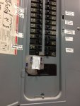
") The AC side is actually on a 40 amp breaker in the house panel. There probably wasn't a big chance it would trip the generator breaker except it would have other loads running at the same time. I am connected with short runs of 6 gauge wire. About a foot and a half from generator to the 50 amp RV outlet, same at the house box, and a 10 ft piece between the two.
The AC side is actually on a 40 amp breaker in the house panel. There probably wasn't a big chance it would trip the generator breaker except it would have other loads running at the same time. I am connected with short runs of 6 gauge wire. About a foot and a half from generator to the 50 amp RV outlet, same at the house box, and a 10 ft piece between the two.