• Steel Soldiers now has a few new forums, read more about it at: New Munitions Forums!

  • Microsoft MSN, Live, Hotmail, Outlook email users may not be receiving emails. We are working to resolve this issue. Please add support@steelsoldiers.com to your trusted contacts.

MEP-803a with only 35V at convenience outlet and 0 at the lugs, Need advice

myridge

New member
14
0
0
Location
Potosi/Missouri
I just picked up a 2003 Fermont MEP-803a with a Tier 2 reset and has 425 hours on the clock. It runs great and reads 60HRZ but it's not producing any power to the lugs and only 35Volts to the convenience outlet.

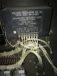
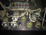
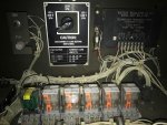
I have downloaded the TM's and I am not sure exactly where to start troubleshooting. I did notice that it looks like a relay was replaced actually it looked loose and it's retaining strap wasn't fastened. I read another post on here from 2016 that had a similar issue but never listed what fixed it. They suspected a bad regulator with shorted FETs.

Also mentioned that when they pressed S1 they would get full power. What is S1? I am not sure what that is. Also, it could just be me but I think I'm smelling a slight burnt smell inside the control panel.

File_004.jpgFile_002.jpgFile_002(1).jpgFile_003(1).jpgFile_000(1).jpg
 

Guyfang

Moderator
Staff member
Moderator
16,028
22,533
113
Location
Burgkunstadt, Germany
Well partner, let's get started by reading some. Manuals and the wire diagram on the door. If you look at the wire diagram, you will find that S1 is the start switch.

Now, you say that you have 60 hertz on the M2 meter, (freq meter). Well, for the M2 to read 60 hertz, your gen set has to be making 120 at the main generator. So my next question is, can you read a schematic? If not we can still work this problem out. Just takes a bit longer. Do you have a multimeter? How are you measuring 35 volts at the 120 volt outlets? With at multimeter? Or the M1, (AC voltmeter)?
 

zarathustra

Active member
Steel Soldiers Supporter
235
58
28
Location
glasgow,ky
Whenever you start seeing smoke or smelling burning, stop doing whatever you are doing....

S1 is the START switch. The START switch does double duty. When in the START position, it runs the starter motor, BUT once the engine is at ~650 RPM the STARTER DISCONNECT kicks in and shuts off the starter and turns on the circuits to flash the field to start generating electricity. That means that this is different from the good ol' car start switch. So, when starting the generator one has to CONTINUE to hold the START switch in the START position after the engine gets running until the VOLTAGE meter registers. First several times I did this I released the START switch as soon as it started -- habit I suppose, but this unit requires the START switch to be held on for a few more seconds to get the field generating. Frankly, one could take a running generator and turn the START switch from RUN to START position (something you'd never do in a car) and nothing would go wrong. That is what the other poster meant when he said he could get electricity when holding the START (S1) switch, but not after he released it.

These units are made to generate a small voltage without the regulator. The output to the convenience outlet follows a different path than the output to the terminals in the lower left of the unit.

If you are getting a small 20 - 30 or so volts out of the convenience outlets then it could be that the regulator is not operating. A quick test of this would be to measure the voltage at the convenience out let when you are first starting the generator. Once the starter disconnect kicks in the unit applies a DC voltage to the excitation windings to get things going while you are still holding the START switch in the START position. At that point you should see around 110 or so volts at the convenience outlets. Once you release the START switch that DC excitation voltage goes away and the regulator kicks in to keep things operating.

If the generator will make 110 or so volts during that short time that you are holding the START switch in START, but quits when you release the START switch, then the regulator is not doing its job. If it never generates the 110 volts at all, then it is likely one of two things...

First, a broken or misplaced wire or loose connector between the output of the voltage regulator and the exciter (the pin number on the regulator escapes me at this time) .

or

Second, a bad stator. Replacing the stator is not too difficult, but one has to remove Sooooooooo many screws, at least 7 or 8 that have rusted together or the threads have stripped inside the nut. I wouldn't start to do that task unless I had the "new" stator in hand, a place where I could get that bearing that goes on the rotor (just in case), a good torque wrench, and a way to lift the stator(s). Last time I did this I used an engine hoist. I've not tried to do it while the engine is still on a trailer, but I think that could be a risky thing to do, what with the weight shifting "back-ards and forwards" and side to side with the CG moving in unusual directions.

There is also a bridge rectifier in the rotor. I don't think they go bad often, but that's a possibility.

good luck

z
 
Last edited:

zarathustra

Active member
Steel Soldiers Supporter
235
58
28
Location
glasgow,ky
Just a quick update on the Hz meter..
If the Hz meter deflects that means you are generating an AC signal of about ~60 Hz. That doesn't necessarily mean that it is 110 Volts -- it could be 20 or so volts.
The Hz meter doesn't "care" about voltage, just cycles.

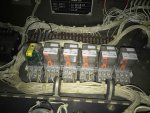
By the way, if you open the control panel and look at the relay bank.... The "relay" on the far left will look different from the rest... That's cause is isn't really a relay, just a small logic circuit in a relay case. That's the starter disconnect switch.

There were two versions of that switch -- one can be installed 180 degrees out. That will give you an Oil Pressure fault light. How do I know??
Since the one version of the switch was NOT made "idiot proof", this "idiot" installed one backwards and spent the next 45 or so minutes trying to find out what this "new" problem with the generator was....
 
Last edited:

Guyfang

Moderator
Staff member
Moderator
16,028
22,533
113
Location
Burgkunstadt, Germany
Just a quick update on the Hz meter..
If the Hz meter deflects that means you are generating an AC signal of about ~60 Hz. That doesn't necessarily mean that it is 110 Volts -- it could be 20 or so volts.
The Hz meter doesn't "care" about voltage, just cycles.

By the way, if you open the control panel and look at the relay bank.... The "relay" on the far left will look different from the rest... That's cause is isn't really a relay, just a small logic circuit in a relay case. That's the starter disconnect switch.

There were two versions of that switch -- one can be installed 180 degrees out. That will give you an Oil Pressure fault light. How do I know??
Since the one version of the switch was NOT made "idiot proof", this "idiot" installed one backwards and spent the next 45 or so minutes trying to find out what this "new" problem with the generator was....


Zara, Everything you wrote that I highlighted in yellow, I agree 1000% And you are not the only one to install S14 wrong. You found it faster then me, anyhow.

But the top part we may need to chew the rag on. The M2, (Hertz Meter) is driven by a DC signal. The M2 gets its input signal from the A-7, (Frequency Transducer). What is a frequency transducer? It is a device to change AC voltage into DC voltage for the purpose of making the M2 meter deflect. The A7 gets its input signal from the A1, terminal 8, and the S8 switch,(Voltage reconnection switch), terminal LO. The S-8 is a pure AC voltage switch. Terminals 7&8 on the A1, are the AC input to the A1. The only way M2 can read 60 hertz, is if the AC signal to the A7 is high enough. If the A1 was simply exciting the G1, then that's what you would get at the S8 and A1 input. That's first off DC voltage, and second off, not enough to make the A7 read 60 hertz. So yes, the M2 has to care about volts.

I suppose our next question should be, when you measured at the output terminals, was the K1, (AC circuit interrupter) closed? When you flipped up the S5, (AC interrupter switch, did the DS7, (AV interrupter light) come on? But I thought we should take it one step at a time.
 
Last edited:

myridge

New member
14
0
0
Location
Potosi/Missouri
I'll try holding the S1 when I get home from work tonight and check voltage again. I am using my Fluke 323 meter to check voltage. I can read the manuals and try and follow a schematic but I'll admit I am no expert in electronics but I can learn and follow instruction. So I really do appreciate all your advice and help you guys are great. THANK YOU.

Also the starter disconnect circuit on the far left the clear one with the yellow sticker in my picture above was the one that seemed loose and didn't have the retention strap on it. I definitely have not held the S1 for any length of time after it started as I didn't know I needed to.

https://www.youtube.com/watch?v=7rOkJZD5LBo
 

zarathustra

Active member
Steel Soldiers Supporter
235
58
28
Location
glasgow,ky
you shouldn't have to hold on to the START for more than 5 seconds after the engine starts running. If nothing happens, then in future tests I still wouldn't hold that switch for more than 5 seconds after it starts running.

I was "camping" on that switch once with a 10 kw generator that wouldn't put out electricity and I looked up and there was some smoke coming out. I shut it down. There wasn't a fire, but the problem was that the stator was shorted internally and getting really, really hot....

good luck, and with any luck you might find out that all you needed to do was run through the start procedure according to the manual.

Also, if that switch (starter disconnect relay-looking item) wasn't seated properly that could cause your exact symptoms..
 

jamawieb

Well-known member
1,413
515
113
Location
Ripley/TN
You do realize your AM/VM switch, on the front panel is in the wrong position??? Your voltage gauge is not going to read correctly, if the s8 reconnection switch is set to 240 single phase as pictured.
 

myridge

New member
14
0
0
Location
Potosi/Missouri
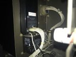
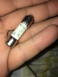
Ok I when I hold the S1 switch I do get full 120v at the convenience plug and 240v on the Guage but when I let go it's gone. First thing I checked was that large fuse next to the regulator and I am not getting continuity through it. I can't read the fuse can anyone tell me what it is I don't see any mention of it in my manual I downloaded but from what I've read on here that fuse was added later to these units is that correct? IMG_1231.jpg
 

Guyfang

Moderator
Staff member
Moderator
16,028
22,533
113
Location
Burgkunstadt, Germany
After replacing the fuse, and it blows again, you need the find a new volt regulater. If it doesn't blow, you should be good. But read the in Info! Yes, it was added later.
 

jamawieb

Well-known member
1,413
515
113
Location
Ripley/TN
Ok I when I hold the S1 switch I do get full 120v at the convenience plug and 240v on the Guage but when I let go it's gone. First thing I checked was that large fuse next to the regulator and I am not getting continuity through it. I can't read the fuse can anyone tell me what it is I don't see any mention of it in my manual I downloaded but from what I've read on here that fuse was added later to these units is that correct? View attachment 692164
Its a 3 amp time delay fuse (KLDR-3). Failure usually caused by shutting the unit down while a load is connected or excessive starting.
 

zarathustra

Active member
Steel Soldiers Supporter
235
58
28
Location
glasgow,ky
At least the unit will generate electricity if primed by the START switch. So you've narrowed the problem to the fuse or the regulator. Because the starter disconnect switch (S14) was partially removed from the unit when you got it it almost looks like someone had tried to trouble shoot the unit before it was declared surplus.

It could just be the fuse, but I wouldn't hold my breath on a new fuse solving the problem.

Regulators can be fixed, but as far as I know there are no shematics available for them, and the transistors are tough to find. For some reason they have been determined to be HAZMAT.

There is a boatload of "stuff" on the circuit board inside the regulator, but the most likely suspects are the two power transistors and five diodes that could be bad.

Diodes for the bridge rectifier are easy to get. There are four identical diodes for the rectifier, and one different diode that goes across the two output terminals of the regulator. If I remember right the primary difference between the bridge rectifier (4) diodes are rated 600v and one across the input terminals is rated 400v (or the other way 'round).

If you are not familiar with tracing circuits and repairing circuit boards, then I'd avoid attempting a repair of the regulator.

They come up for sale periodically -- I got a NOS one from ebay for around 100 a year or so ago...

Watch out for the 400Hz regulators - they come up on ebay, and sometimes the lister "forgets" to mention that they are 400Hz and not 60Hz.
 

myridge

New member
14
0
0
Location
Potosi/Missouri
I'll pickup a few fuses today and cross my fingers that it was just a hard start or other similar condition that blew that fuse and that the A1 or Stator isn't damaged. That (TB 11-6115-741-24) has great testing procedures so I'll try those. I'll report back once I have replaced the fuse.
 

zarathustra

Active member
Steel Soldiers Supporter
235
58
28
Location
glasgow,ky
A few fuses..... Y'all aint priced 'em yet...

Home Depot won't have them. You'll have to go to an electrical supply house. Remember, you want the "slo-blo" fuse. The clerks at some of those supply houses think that a fuse is a fuse, is a fuse, but that aint so.

Since you can make 110vac with the START switch, I'd say the stator is just fine. If the regulator is bad, then you can thank the fuse for the good stator. The fuse did its job.

z
 

dav5

Active member
396
181
43
Location
Mono, Ontario
The fuses are way overpriced. My 2006 803A didn't have the fuse mod. I got the proper fuse holder and fuses on Ebay. Not the exact fuse but 3.6 slow blow. I assumed it would work and the price was right.
 

Guyfang

Moderator
Staff member
Moderator
16,028
22,533
113
Location
Burgkunstadt, Germany
Its a 3 amp time delay fuse (KLDR-3). Failure usually caused by shutting the unit down while a load is connected or excessive starting.

A bad bad volt regulater will also pop the fuse. That is the reason it's there. To keep the stator from being toasted, when the volt reg goes into an over volt situation.
 

myridge

New member
14
0
0
Location
Potosi/Missouri
Thank you everyone. I'm thrilled to report that with a new fuse I'm generating 120v at Lugs and the convenience recepitcal. I couldn't be happier with my purchase of this generator with a tier 2 reset 425 hours and it's producing power again for under $900 including gas to go get it I'm one happy fellow.

Your right those fuses are pricy one vendor wanted $26 I found it local at the electrical supply for $11 and ordered 2 spares to put in the storage compartment on amazon for $6 each along with all new filters. You all are the greatest thanks again.
 

Daybreak

2 Star Admiral
Steel Soldiers Supporter
1,521
741
113
Location
Va
Howdy,
A few points.
All that cranking you did might have blown the fuse.

In the future, when you replace the fuel filters... the unit is self priming. OH, the fuel water separator (spin-on) is sometimes a real bear to get off. Self priming, turn to prime and let is run a while. It takes some time to fill up both filters. When starting, you turn to start and stay there until oil pressure is up, then let go and continue.

MEP-802/803 Filters and Parts the second post has a bunch of links to other little items.
 
Top