loosegravel
Just a retired mechanic who's having fun!
- 504
- 887
- 93
- Location
- Enumclaw, Washington
1) I recently had a under voltage fault on a MEP-804A 15kw unit. I thought that I should chronicle the event here in an effort to give back to this great forum. Forgive me if this post is a little long. I’ll label each paragraph and if someone wants to chime in you can refer to that paragraph.
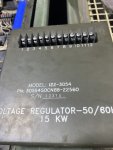
2) Initially when this under voltage fault occurred, I PM’ed another member here because I thought that I would be purchasing an A1 A/C voltage regulator from him. I’m not sure that this gentleman would want me to raise his flag up the pole, so I won’t mention his name. But he has been instrumental in my troubleshooting; he’s devoted a lot of his time in an effort to help me and I’m grateful for his time.
3) I titled this thread as an under-voltage fault, but the truth is that it actually began as an over-voltage shut down at start-up. While I’m thinking about it here, I understand that the “over-voltage” shut down is on the engine side. Am I correct? I acquired this unit a few weeks ago along with an additional MEP-804A 15kw. Both of them are trailer mounted. After installing some new batteries, fluids and filters I had the subject unit up and running in no time. I ran it and load tested it up to 125% of its rated load for a short time, then dropped the load to 100% and let it run there for about an hour. No issues came up at all. I then went to the other unit and attempted to get it operational. Initially I had no 24vdc up to the main control panel and the MPU was not putting out, so I borrowed it from the subject unit. After restoring the 24vdc to the main panel and replacing the MPU, I was able to get the second unit up and running. Just like the subject unit, I load tested it and everything was great. I ordered a replacement MPU and it arrived a few days later.
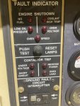
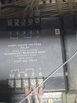
4) I installed the new MPU into my subject unit and adjusted it to obtain the required 2.8vac while cranking over the engine. I plugged it in and prepared to start the unit up. It was fairly cold (maybe 25 degrees F) and the unit cranked over for about 15 seconds before it fired up. It immediately faulted for over-voltage and the unit shut down. I started the unit again and held S1 in the start position for about 5 seconds and then let it go. The unit shut down a second time for over-voltage. I started it for the third time and held S1 in the start position for a longer period of time. (Maybe 15 seconds but more than 5) This time, I could hear a “snap” noise of maybe a “crack” noise coming from inside the unit somewhere and I let go of the S1. The over-voltage fault was now gone, and the engine didn’t shut down this time. But I now had an under-voltage fault. At this time, I still don’t know if I induced a problem by holding S1 in the start position for too long of a period, or if right before my very eyes the A1 voltage regulator was at the end of its life?
5) I had no action on the volt or frequency meters with the engine running. I had no power to the convenience receptacle, even with S1 in the start position. I pulled up the TM for a Libby A1 A/C voltage regulator and began doing the tests. I disconnected wire 141A from the A1 in step “g” and in step “h” I had 10vdc measuring between wire 141A and terminal 3. In step “j” I had only 3.6vac when measuring between terminals 10 & 11 on the A1 with the unit running and S1 held in the start position. I was supposed to see 210-280vac at that point. What was interesting to me here was that with 141A removed from A1, my volt and frequency meters were now working. I also had power at the convenience receptacle. (Although at this time I was just using a halogen lamp on the convenience receptacle, so I didn’t know what my voltage there actually was) In step “i” my voltage potentiometer was smooth at 3.6K ohms in the full CCW position all the way up to 12K ohms in the CW position.
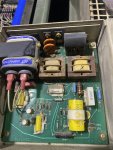
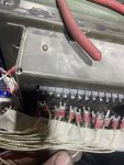
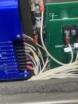
6) As per some information that I received, I went to the T1 transformer to do some checks there. (Wire 141A was still removed from A1 at this point) I checked terminals 1 & 2 on the T1 with the unit running and the S1 in the start position. I only saw 165vac at that point, when I should have seen upwards of 208vac. That reading would climb the longer I held S1 in the start position. When 141A was reconnected to A1, the reading on terminals 1 & 2 went way down to 17.5vac. I checked across terminals 3 & 7 on the T1 with the unit running and the S1 in the start position. I only saw 6vac with 141A removed from A1 and about ¾ of a volt with it connected.
7) As per some instruction I went ahead and removed all (7) of the wires from the T1 transformer in an effort to isolate it. Again, I checked across wires 1 & 2 (now removed from the T1 and with 141A still removed from A1) I now had 210vac on those two wires with the unit running and S1 in the start position. At this point I also decided to measure the actual voltage at the convenience receptacle. It was right at 120vac with the unit running and S1 in the start position. With wire 141A reconnected to A1, my voltage at the convenience receptacle dropped to about 90vac and would continue to climb the longer I held S1 in the start position. Also, the voltage to wires 1 & 2 (still disconnected from T1) dropped to about 165vac and would continue to climb the longer I held S1 in the start position. Because wires 3-7 on the T1 pass up through the J5/P5 cannon plug, I ohm checked them from T1 to A1. All had low resistance.
") Myself and the super cool dude who’s been helping me trouble-shoot this problem both agreed to try a new A1 voltage regulator. I’m waiting for it, should be here in a few days it looks like. I’ll report back when I get it and test this unit. Thanks all for this great forum! Jeff
Myself and the super cool dude who’s been helping me trouble-shoot this problem both agreed to try a new A1 voltage regulator. I’m waiting for it, should be here in a few days it looks like. I’ll report back when I get it and test this unit. Thanks all for this great forum! Jeff
2) Initially when this under voltage fault occurred, I PM’ed another member here because I thought that I would be purchasing an A1 A/C voltage regulator from him. I’m not sure that this gentleman would want me to raise his flag up the pole, so I won’t mention his name. But he has been instrumental in my troubleshooting; he’s devoted a lot of his time in an effort to help me and I’m grateful for his time.
3) I titled this thread as an under-voltage fault, but the truth is that it actually began as an over-voltage shut down at start-up. While I’m thinking about it here, I understand that the “over-voltage” shut down is on the engine side. Am I correct? I acquired this unit a few weeks ago along with an additional MEP-804A 15kw. Both of them are trailer mounted. After installing some new batteries, fluids and filters I had the subject unit up and running in no time. I ran it and load tested it up to 125% of its rated load for a short time, then dropped the load to 100% and let it run there for about an hour. No issues came up at all. I then went to the other unit and attempted to get it operational. Initially I had no 24vdc up to the main control panel and the MPU was not putting out, so I borrowed it from the subject unit. After restoring the 24vdc to the main panel and replacing the MPU, I was able to get the second unit up and running. Just like the subject unit, I load tested it and everything was great. I ordered a replacement MPU and it arrived a few days later.
4) I installed the new MPU into my subject unit and adjusted it to obtain the required 2.8vac while cranking over the engine. I plugged it in and prepared to start the unit up. It was fairly cold (maybe 25 degrees F) and the unit cranked over for about 15 seconds before it fired up. It immediately faulted for over-voltage and the unit shut down. I started the unit again and held S1 in the start position for about 5 seconds and then let it go. The unit shut down a second time for over-voltage. I started it for the third time and held S1 in the start position for a longer period of time. (Maybe 15 seconds but more than 5) This time, I could hear a “snap” noise of maybe a “crack” noise coming from inside the unit somewhere and I let go of the S1. The over-voltage fault was now gone, and the engine didn’t shut down this time. But I now had an under-voltage fault. At this time, I still don’t know if I induced a problem by holding S1 in the start position for too long of a period, or if right before my very eyes the A1 voltage regulator was at the end of its life?
5) I had no action on the volt or frequency meters with the engine running. I had no power to the convenience receptacle, even with S1 in the start position. I pulled up the TM for a Libby A1 A/C voltage regulator and began doing the tests. I disconnected wire 141A from the A1 in step “g” and in step “h” I had 10vdc measuring between wire 141A and terminal 3. In step “j” I had only 3.6vac when measuring between terminals 10 & 11 on the A1 with the unit running and S1 held in the start position. I was supposed to see 210-280vac at that point. What was interesting to me here was that with 141A removed from A1, my volt and frequency meters were now working. I also had power at the convenience receptacle. (Although at this time I was just using a halogen lamp on the convenience receptacle, so I didn’t know what my voltage there actually was) In step “i” my voltage potentiometer was smooth at 3.6K ohms in the full CCW position all the way up to 12K ohms in the CW position.
6) As per some information that I received, I went to the T1 transformer to do some checks there. (Wire 141A was still removed from A1 at this point) I checked terminals 1 & 2 on the T1 with the unit running and the S1 in the start position. I only saw 165vac at that point, when I should have seen upwards of 208vac. That reading would climb the longer I held S1 in the start position. When 141A was reconnected to A1, the reading on terminals 1 & 2 went way down to 17.5vac. I checked across terminals 3 & 7 on the T1 with the unit running and the S1 in the start position. I only saw 6vac with 141A removed from A1 and about ¾ of a volt with it connected.
7) As per some instruction I went ahead and removed all (7) of the wires from the T1 transformer in an effort to isolate it. Again, I checked across wires 1 & 2 (now removed from the T1 and with 141A still removed from A1) I now had 210vac on those two wires with the unit running and S1 in the start position. At this point I also decided to measure the actual voltage at the convenience receptacle. It was right at 120vac with the unit running and S1 in the start position. With wire 141A reconnected to A1, my voltage at the convenience receptacle dropped to about 90vac and would continue to climb the longer I held S1 in the start position. Also, the voltage to wires 1 & 2 (still disconnected from T1) dropped to about 165vac and would continue to climb the longer I held S1 in the start position. Because wires 3-7 on the T1 pass up through the J5/P5 cannon plug, I ohm checked them from T1 to A1. All had low resistance.