• Steel Soldiers now has a few new forums, read more about it at: New Munitions Forums!

  • Microsoft MSN, Live, Hotmail, Outlook email users may not be receiving emails. We are working to resolve this issue. Please add support@steelsoldiers.com to your trusted contacts.


MEP-805 Frequency Fluctuation

Feenix206

New member
12
3
3
Location
Michigan
Parameters:
MEP-805
Voltage Setting 450-480
HZ Setting 60HZ
Load 60% 20KW continuous and 4 1.5Hp motors intermittently Max Load always less than 25KW

Issue:


Generator starts to produce power and stays steady at 60 HZ and adjust automatically as it should. After 15 min to 2 hours it will occasionally drop to 52 HZ and can not be manually adjusted up to 60hz. Occasionally it mysteriously comes back to 60hz on its own. Also, when this happens, if load is taken off line by opening circuit, hz rise to over 60hz. It seems like generator just stops controling engine rpm hence hz is unstable. Sometimes shutting down unit and restarting will get it back to 60hz but not always. I am new to this site and new to this MEP-805. Any help will be greatly appreciated. Also does anyone know of a place where I can call who supports these MEP Generators. I have 3 and it would be helpfully to know where to get service.

Thank You
 
Last edited:

jmenende

Well-known member
447
364
63
Location
Puerto Rico
Check the mag pickup. Could be sending incorrect reading to the governor and thus messing with the actuator. Check for 2.8-3vac. If not, remove, clean and readjust tgr mpu. The TM has the procedure. If this does not help, try to rule out the IP by releasing the linkage and setting it manually to 60hz and see if it holds. The pump may need a rebuild and the tolerances may be affected once the unit heats up. Id treat the fuel with tranny fluid first before rebuild.
 

Feenix206

New member
12
3
3
Location
Michigan
Check the mag pickup. Could be sending incorrect reading to the governor and thus messing with the actuator. Check for 2.8-3vac. If not, remove, clean and readjust tgr mpu. The TM has the procedure. If this does not help, try to rule out the IP by releasing the linkage and setting it manually to 60hz and see if it holds. The pump may need a rebuild and the tolerances may be affected once the unit heats up. Id treat the fuel with tranny fluid first before rebuild.


Thank you for pointing me to the mag pickup. While trying to adjust the gap, it was necessary to roll crank to align the flywheel tooth. This made me discover that the alternator belt was so loose that you could almost flip it off the pully. I dont think I actually changes the previous gap setting, but tighting the alternator belt seemed to fix the problem. Does battery voltage come into play with the generator control circuits?
 

jmenende

Well-known member
447
364
63
Location
Puerto Rico
Thank you for pointing me to the mag pickup. While trying to adjust the gap, it was necessary to roll crank to align the flywheel tooth. This made me discover that the alternator belt was so loose that you could almost flip it off the pully. I dont think I actually changes the previous gap setting, but tighting the alternator belt seemed to fix the problem. Does battery voltage come into play with the generator control circuits?
Ohh boy. Low voltage makes havoc on the 805b and 806b cim module. Causes it to restart etc. So yes, weak batteries and an alternator not rotating at the correct speed will affect the unit.
 
Last edited:

Feenix206

New member
12
3
3
Location
Michigan
Ohh boy. Low voltage makes havoc on the 805b and 806b cim module. Causes it to restart etc. So yes, weak batteries and an alternator not rotating at the correct speed will affect the unit.

Now I have a new issue. This time its with one of my two 804Bs. Both of them, one with an Isuzu and the other one with a Yanmar have had issues with delayed actuation of the contactor toggle switch and corresponding green light. Sometimes it would come on in a few minutes, or upon reactuating the toggle, but with both units always never more than 5 minutes. There is never any rhyme nor reason to why the green light finally came on, or any relation to restarting, reseting or any thing else. It just happened. Now the Isuzu units contactor will not come online at all. I have 480v, 60hz showing but no green light. Resetting does not help. Any ideas on where to start?
 

Guyfang

Moderator
Staff member
Moderator
15,903
22,183
113
Location
Burgkunstadt, Germany
One of the sets is an MEP-804A, and the other is a MEP-804B.

Where is "480 showing". The meter? The output terminals?

The DS7 only can come on, when the S5 is placed in the Up/On position, AND the K1 CLOSES. So, when you actuate the S5, and don't get a DS7 light to come on, is there output at the load terminals? If there is no output to the load terminals, then the DS7 wont come on. If there is output at the load terminals, then you have a loose connection someplace, OR, the contacts in the K1 are not working/closing. K1 AUX contacts, pins 11 & 12.

1688763986861.png
 

Feenix206

New member
12
3
3
Location
Michigan
There is no output to the load terminals. But 480v on meter. This has been an ongoing problem with both units but prolonged holding of toggle to close circuit sometimes fixes it and occasionally the circuit closes by itself after toggle is actuated moments later. This time it never closes so no green light and no voltage to load terminals yet meter shows 480v 60hz
 

Guyfang

Moderator
Staff member
Moderator
15,903
22,183
113
Location
Burgkunstadt, Germany
Then this is a clear sign you need to take the K1 out, disassemble it, clean it up, reassemble it and see if it will work right. Perhaps you need to delve in to the -24 TM and read how the system works. You are worried about DS7, when in fact you have no output. DS7 is telling you that. Fix K1, or get a new one.
 

Feenix206

New member
12
3
3
Location
Michigan
Then this is a clear sign you need to take the K1 out, disassemble it, clean it up, reassemble it and see if it will work right. Perhaps you need to delve in to the -24 TM and read how the system works. You are worried about DS7, when in fact you have no output. DS7 is telling you that. Fix K1, or get a new one.


Could you direct me where to find the -24 TM. I looked in the TM section of this site and wasn’t able to find it for the MEP-804 A or B. Some help locating the K1 would be helpful as well. I wasn’t able to troubleshoot it again till today when there was no DS7 or output to lugs as for the last week it went back to working flawlessly.
 

Feenix206

New member
12
3
3
Location
Michigan
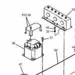
Open up the right rear top door. K1 should be in there. It will have K1 written next to it. Its item 36 in this picture.
View attachment 901444
Thank you. That helped a lot. So prior to checking out the k1; I thought I’d check out the switch first. I found that two poles were apparently associated with 24v- and the other two are 24v+. I found it odd that the 24v+ side tested 24v+ on both poles regardless of switch position With engine not running. This test made when actuating switch did not activate K1. I removed one of the 24v+ wires to isolate and test the DPDT switch which checked out ok. At this point I put the 24v+ wire back on the switch and strangely enough the switch no longer tested 24v+ on both terminals. I tried to start and actuate switch, and now it actuated the K1 and DS1 ant everthing worked fine. I assumed a connection issue at the switch and thought problem solved. System worked fine next two starts till today. Again the switch did not activate the K1. This time I immediatly checked voltage on switch and again found 24v+ on both + poles of switch regardless of switch position. Removing one + wire and reinstalling corrected the presence of 24 v+ on both wires, and when started switch activated the K1 and back in business. Any ideas why disconnecting one of the 24v+ wires from switch and reconnecting solves problem.
 

Guyfang

Moderator
Staff member
Moderator
15,903
22,183
113
Location
Burgkunstadt, Germany
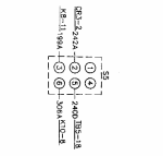
Peter, we may need to show S5. Hooked to S5-2, is wire # 242A.
1689886855383.png

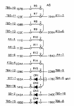
That wire runs over to a panel in the left side of the control cube. This is what it looks like. Remove the wire 242A from the S5-2 and then test the CR3

1689886662446.png

Do you know how to test a diode?
 
Last edited:

Feenix206

New member
12
3
3
Location
Michigan
With s1 off and 242a20 removed from s5. I tested diodes cr1 = .471, CR2 =.471, CR3 = .51, CR4 = .47. Just a slight difference in CR3 from other diodes. Would that make a difference?

also with more detailed testing at S5, S5-2 wire has 24v+ and all others have nothing when disconected from S5 with S1 on run but not running
 
Top
AdBlock Detected

We get it, advertisements are annoying!

Sure, ad-blocking software does a great job at blocking ads, but it also blocks useful features of our website like our supporting vendors. Their ads help keep Steel Soldiers going. Please consider disabling your ad blockers for the site. Thanks!

I've Disabled AdBlock
No Thanks