• Steel Soldiers now has a few new forums, read more about it at: New Munitions Forums!

  • Microsoft MSN, Live, Hotmail, Outlook email users may not be receiving emails. We are working to resolve this issue. Please add support@steelsoldiers.com to your trusted contacts.


MEP-805b current draw

datagen24

New member
18
0
0
Location
Merrimack NH
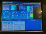
MEP-805b DC current draw

Just acquired an MEP-805b very clean from government liquidations

Got it all lubed up and going last night but noticed a very heavy draw on the battery (-10 amps with engine running, -13 with stopped)
Google led me to a tech note that said the charging fuse may have been blown.

Best I can tell that tech note had been applied as the breaker and the wiring changes appear to have been made.

So that leads me to my question. Does the Dc current gauge normally read reversed i.e. A negative draw in normal operations?

More info
Another hint I have is the voltage appears to be a charge when checked at the battery terminals.
There is so much elephant snot I can't get probes in right at the alternator.
I have tested now again this morning at the batteries ,the nato connector and just after the battery current transformer i am reading a charging voltage of 27.5 v
batteries read 25.1 this morning after sitting all night in sub freezing temperatures.
testing this morning the draw is also lower -4 amps
 

Attachments

Last edited:

Korgoth1

New member
191
2
0
Location
radford, va
If the batteries were dead when you started it, it could cause strange readings. I would load test it for a few hours and then start diagnosing, it may clear itself up...

Would love to have some pictures of inside the enclosure... Just curious, Do you feel that it is actually the rated 70db? I have personally measured a 803a and it was 70db. I wish there was more load data on these bigger units. I bet it would weld 1/2 inch nelson studs.
 
Last edited:

datagen24

New member
18
0
0
Location
Merrimack NH
The batteries are brand new, Gov liquidation stripped it and drained it.
No oil, no fuel, no coolant, no batteries, all the tool boxes where empty.

so they are brand new optima red tops in it. filled it with 15w-40 oil mobil delvac 1300 (same stuff i use on my Mercedes diesels, and John Deer Tractor).

I will get some good photos with better light tomorrow for you, quite surprised how clean the unit is over all, only two rust spots on it

Year built was 2007. so far the voltage regulation is superb same with frequency I am running a small computer room, it is feeding directly into a 30kva 3 phase UPS which is not complaining about the power quality.

noise level is quite a bit lower than a cummins onan this is replacing. I will get my db meter is out as well
 

datagen24

New member
18
0
0
Location
Merrimack NH
Quick note, in multiple runs the issue still presents it self but i have not had to charge the battery, my guess is a sensor is miss-wired showing a negative draw on the battery when it should be positive that or the field in the CIM is mislabeled and that should read alternator current draw
sensor being directly after the alternator before any other connection.
 

RickM39

New member
7
0
1
Location
Quakertown, PA
You are right, the sensor must be wired backwards.

The battery voltage would not be 27 if it were discharging.

Does the ammeter approach zero if it runs for awhile and the battery voltage increase to 28 or so?
 

Guyfang

Moderator
Staff member
Moderator
15,932
22,252
113
Location
Burgkunstadt, Germany
The CIM is not mislabeled. Check to see if the 16 gage wires at the Batteries and the connection strip on the left side are correctly connected. Use the wire diagram that's on the door, to check it. When the fuse holder MWO was applied to these sets, the wire diagram and schematics were also upgraded to reflect the changes. If you can not find the fuse on the diagram, the set may have been improperly upgraded.
 

datagen24

New member
18
0
0
Location
Merrimack NH
I cant find a fuse just the 50 amp breaker (CB1) connected directly to the output of the alternator
the wire to the 50 amp breaker passes through the current transformer before going to CB1,

Right after CB1 is the branch to the control box, then down to the batteries.
 

Guyfang

Moderator
Staff member
Moderator
15,932
22,252
113
Location
Burgkunstadt, Germany
OK, the fuse was an interim fix, the CB was the final fix. Are they on the wire diagram? Are they hooked up right? Check all the wires, to include the wires to the Battery charging alternator.
 

datagen24

New member
18
0
0
Location
Merrimack NH
They are on the wiring diagram

I am not having a problem with draw down just the gauge shows a draw on the battery when none is present. i can start the unit up no problem, let it run for a little bit and shut it down. been doing it weekly for a few weeks and it has not given me trouble.
 

Guyfang

Moderator
Staff member
Moderator
15,932
22,252
113
Location
Burgkunstadt, Germany
I am not trying to to get you to look for a draw down. I am trying to get you to check the wires that go to the BCT, (battery Current Transformer. I think the signal that goes to the CIM for battery charging meter/readout, comes from the BCT. If the wires are reversed, the signal will drive the meter down, instead of up. Its hard for me to read the schematics, as my old eyes just ain't what they used to be. Have you looked at the schematics, to see where the signal originates?
 

datagen24

New member
18
0
0
Location
Merrimack NH
I just have not ventured outside -10 air temp right now :)

the diagrams i have been looking at indicate it comes from the BCT.

I wanted to note that even though the CIM indicates a draw i was not seeing the effects of one, hence i think it is in the monitoring components.

I am going to try and trace the BCT lines tomorrow when it should be warmer. Also look for a part number so i know the ranges
then i should be able to tap in with my meter and see the raw values for my self
 

Guyfang

Moderator
Staff member
Moderator
15,932
22,252
113
Location
Burgkunstadt, Germany
Here is a tip. Take pictures of the schematics and wire diagrams. Print them out and put them in document protectors. Then when you are working/looking all over in the cold, you do NOT have to continually go back around to the G.D. doors and look at the plates. When I worked for the military, I "procured" a schematic and wire diagram plate from every type of set. Had them on a zip-tie ring. Handy, as it drove me crazy going back and forth. Its not quite as cold here. Only a tad below freezing. 3 weeks ago it was -20 Cel. in the sun. With the wind? Oh yeah, this old soldier was cold. Good luck!
 

datagen24

New member
18
0
0
Location
Merrimack NH
in MMR i had the nice big cavernous hot (100+ F) engine room, and a nice large library with every schematic i needed...
and things all in the books, i was just used to working on bigger systems these little guys you cant climb inside to trace stuff :) checking piston rod involved opening a hatch and looking climbing inside the engine, not that it applies tracing a circuit but you get the idea.

Now i work in a data center with racks of howling machines kept at a constant 68 degree 30% RH, and an insatiable hunger for electricity... 250kw per rack
 

Guyfang

Moderator
Staff member
Moderator
15,932
22,252
113
Location
Burgkunstadt, Germany
That's the secret! Proper tools, proper knowledge, (books and schematics) and experience helps out too. I spent 20 years in the Army, doing power generation. Got out and stayed in Germany. Went to trade school here and became an electrician. Got tired of that and started contracting for the Army. When that went tits up, I got a job in the Solar Power, Biogas Power and transformer field. Its been fun, but this old soldier is ready to at last retire. Although a gig in a data center would sound interesting!
 

Guyfang

Moderator
Staff member
Moderator
15,932
22,252
113
Location
Burgkunstadt, Germany
You know, I installed a lot of these upgrades for the 805 and 806's. I also found a lot of them improperly installed. I am almost sure that the battery charging scale reading backwards is because of this upgrade being installed wrong. Its been too many years ago. My brain is just to fried. I used to have the instructions for this upgrade. Have to see if its in my computer.
 

Hard Head

Member
Steel Soldiers Supporter
540
21
18
Location
Greenville SC
TB 11-6115-741-24 (2009)

TB 11-6115-741-24
5.4 Battery Charging Fuse Modification 30-60 kW "B" model Tactical Quiet Generator Sets MEP-805B,
MEP-815B, MEP-806B, MEP-816B


5.4 Scope:


The MEP-805B, MEP-815B, MEP-806B, MEP-816B, models of the Tactical Quiet Generator (TQG) family of
generator sets have a problem with the battery charging fuse. The battery charging fuse has a high
rate of blowing. This requires the soldier to keep many spare fuses on hand for replacements. A
blown fuse caused two problems. The obvious problem is the loss of the ability to charge the
batteries. The more critical problem is the loss of DC control power during mission operations.


The blown battery charging fuse problem is caused by the charging characteristics of the Optima
battery. The Optima batteries have a low internal resistance enabling the battery to receive a
higher than normal charging current. The alternator has a continuous current capacity of 45 Amps,
with a peak of 60 Amps. With the Optima battery and this alternator, the battery charging current,
at times, can exceed the maximum current capacity of the fuse therefore the fuse blows. The 6TMF,
6TL, etc., batteries have a higher internal resistance and will not accept current higher than the
current capacity of the fuse. The solution to this problem is to replace the 30 A fuse and the 18
gauge wire with a 50 A circuit breaker and a 12 gauge wire. The procedures and materials are
described below.


The control power loss problem is caused by the location of the control power circuit take off. The
control power is connected to the battery terminal and not the battery charging alternator. While
the generator set is operating, the battery charging alternator provides the DC control power
through battery charging system. When the fuse blows, the source of generator set DC control power
becomes the batteries until available battery power is consumed. With no DC control power, the
generator set shuts down. There is another set of instructions to move the DC control power wire to
the back of the alternator in order to prevent this failure mode.


3.7.11 On 15, 30 & 60 kW TQG’s only: with TRC voltage regulators, install fuse on exciter circuit
on F1. See Paragraph 5.3.


3.7.12 On 15, 30 & 60 kW TQG’s Voltage Regulator only: A1, clean dust/sand from circuit card.


3.7.13 On 30 & 60 kW TQG "B" Models only: replace the inline 30 amp battery-charging fuse with a
50-amp circuit breaker. See Paragraph 5.4. Also, if a newly redesigned module is not installed, the
Backplane Module shall be replaced 100% with the newly redesigned module, same NSN. The newly
redesigned module utilizes surface mount components in lieu of the discrete capacitors and
resistors. If the Master Switch is turned on and the CIM does not boot up (black display), refer to
Appendix N for CIM checking procedures.
 

baxter462

Member
79
2
8
Location
Salt Lake City Utah
Hello,

I have two MEP-805B generators, a 2008 model year with the 50 amp circuit breaker on the charge circuit, and a 2002 that had an inline glass fuse. On the 2008, the charge gauge reads incorrectly just as described earlier in this thread. The 2002 read correctly (after I replaced the blown fuse when I purchased the generator). I have since acquired the parts to "upgrade" my 2002 with the bracket, circuit breaker, and larger gauge wire so I won't have to worry about another blown fuse. I did the modification exactly as per TB-11-6115-741-24 (which is also exactly as my 2008 appears), and now both of my generators charge gauges are inaccurate. This is because originally, the control system wire (powering up the CIM and other control modules) originally ran through the current transformer/transducer (there were originally 2 wires going through it), so the current needed to power up those devices added to the "charge" amount shown on the gauge. For reasons explained in TB-11-6115-741-24, the control wire is now connected to the alternator lug (so an open circuit breaker during operation won't cause the generator to shut off when the batteries eventually die due to a non-charging situation), which means the current transducer is no longer measuring that current. With the larger gauge charge wire now going through the hole of the current transducer, I don't think the control system power wire would physically fit through the hole also (which would be the way to fix this problem properly).

Anyway, it seems like around -6 to -8 amps is the "new zero" on the CIM ammeter after TB-11-6115-741-24 has been performed. The modification is flawed from a charge/discharge measurement standpoint because the current transducer will measure the control system draw when the charging system is not active, but once the charging system is active, the batteries are the only load the current sensor is measuring, and the system wasn't calibrated/zeroed that way. So, I guess what I'm trying to say is, if the ammeter is above about -6 to -8 amps, your charging system is working (and you'll see a voltage reading that reflects a functioning charging system). If the ammeter reads below-8 amps, it probably isn't charging. It is a little frustrating that an "upgrade" causes the instrumentation to be inaccurate, but the benefits of the upgrade are worth it.
 

Guyfang

Moderator
Staff member
Moderator
15,932
22,252
113
Location
Burgkunstadt, Germany
Baxter,

I sent your comment to someone I know who is in the biz. Below is part of my mail to him and his answer. He also attached two documents, only one of which I can download, and its attached here. Take a gander at his answer, and see if it helps you any.


Guy, (this is his answer to me.)

He seems to have the STIR so the attached is what we got on the subject. A minus 6-8 AMPS may mean the wire is passing thru backwards (reversed) so current passing B- to B+ is backwards, but it seems to be charging at a normal rate. They like to run about 2-4 hours before it goes to a lower charge rate as the Active Glass Mat Optima's react that way. The BCT transformer is supposed to measure only the charging of the batteries, and its signal is displayed on the screen. If the Alternator to CB1 wire passes the correct way then the BCT may be wired backwards. There is no adjustment of the BCT circuit to the backplane, to the I/O to the CIM.


-----Original Message-----
From: guyfang [mailto:guyfang@aol.com]
Sent: Saturday, January 07, 2017 2:12 PM


Dave, (My mail to him)


The following comment is bugging me. I did probably a hundred of these upgrades to 805 and 806's, I simply do not remember it causing this problem. I do remember seeing the problem, and seem to remember it was almost always because the MWO was falsely installed. I fixed several that I found with a "high" reading on the CIM, and it was always a wiring problem. Or am I simply mixing things up in my head. This has been bugging me.!


Later!


Guy


Hello, (Your original statement)

I have two MEP-805B generators, a 2008 model year with the 50 amp circuit breaker on the charge circuit, and a 2002 that had an inline glass fuse. On the 2008, the charge gauge reads incorrectly just as described earlier in this thread. The 2002 read correctly (after I replaced the blown fuse when I purchased the generator). I have since acquired the parts to "upgrade" my 2002 with the bracket, circuit breaker, and larger gauge wire so I won't have to worry about another blown fuse. I did the modification exactly as per TB-11-6115-741-24 (which is also exactly as my 2008 appears), and now both of my generators charge gauges are inaccurate. This is because originally, the control system wire (powering up the CIM and other control modules) originally ran through the current transformer/transducer (there were originally 2 wires going through it), so the current needed to power up those devices added to the "charge" amount shown on the gauge. For reasons explained in TB-11-6115-741-24, the control wire is now connected to the alternator lug (so an open circuit breaker during operation won't cause the generator to shut off when the batteries eventually die due to a non-charging situation), which means the current transducer is no longer measuring that current. With the larger gauge charge wire now going through the hole of the current transducer, I don't think the control system power wire would physically fit through the hole also (which would be the way to fix this problem properly).

Anyway, it seems like around -6 to -8 amps is the "new zero" on the CIM ammeter after TB-11-6115-741-24 has been performed. The modification is flawed from a charge/discharge measurement standpoint because the current transducer will measure the control system draw when the charging system is not active, but once the charging system is active, the batteries are the only load the current sensor is measuring, and the system wasn't calibrated/zeroed that way. So, I guess what I'm trying to say is, if the ammeter is above about -6 to -8 amps, your charging system is working (and you'll see a voltage reading that reflects a functioning charging system). If the ammeter reads below-8 amps, it probably isn't charging. It is a little frustrating that an "upgrade" causes the instrumentation to be inaccurate, but the benefits of the upgrade are worth it.
CLASSIFICATION: UNCLASSIFIED
 

Attachments

Last edited:
Top
AdBlock Detected

We get it, advertisements are annoying!

Sure, ad-blocking software does a great job at blocking ads, but it also blocks useful features of our website like our supporting vendors. Their ads help keep Steel Soldiers going. Please consider disabling your ad blockers for the site. Thanks!

I've Disabled AdBlock
No Thanks