• Steel Soldiers now has a few new forums, read more about it at: New Munitions Forums!

  • Microsoft MSN, Live, Hotmail, Outlook email users may not be receiving emails. We are working to resolve this issue. Please add support@steelsoldiers.com to your trusted contacts.


MEP 831a No Power To Main Bus

Lostranger

Member
32
0
6
Location
Marion, NC
I’ve been using an MEP 831a as backup for our off-grid solar system for four years. It has always given trouble, but the problems were less after I bought a governor control module from a member of this forum. His name may be Klopp.

Three years ago, I bought a second machine for backup. It was cheap, but it had starter trouble, and it had power to the courtesy outlet, but never at main bus. In a short while, the engine stopped working, and I moved it to storage.

About a month ago, what I think is the inverter of the first machine made a rapid series of popping sounds, then it quit making power.

I wasted a lot of time trying to start the second machine. Now I have put the motor from the first machine into the second. Engine starts easily and runs best ever, but still no power at main bus.

I swapped a large relay from inside main compartment. I also swapped toggle switch from control panel and all three relays from behind control panel.

Any thoughts? Help greatly appreciated. I’m also in the market for a starter. I have one that does not work and one weak one.

Jim in NC
 

Lostranger

Member
32
0
6
Location
Marion, NC
Do you have a hand held meter and are you proficient at using it?
I have a good Fluke meter, but I’m not the best at troubleshooting. I have since learned that I have good voltage on top of inverter at L1-N-L2. I tested both 120 and 240 settings. I’ve been distracted today. Hope to find in manual where to test contactor even though I swapped the one from the machine that was generating until inverter blew.
 

kloppk

Well-known member
Steel Soldiers Supporter
1,967
3,063
113
Location
Pepperell, Massachusetts
First thing to look at is the far left relay inside the panel.
This is K12 the fault relay. If the tiny LED inside it is lit then there is a fault and the contactor will not close.
Is K12's LED on when the set is running?

If K12's LED is off...
Here are a sequence of test steps to narrow down where the problem is with the contactor not closing.

Turn the set OFF.

1) Battle Short OFF
2) Connect your DC voltmeters negative lead to chassis ground.
3) Set you meter so it can read DC volts.
4) Start the generator
5) Measure the DC voltage at the following points in order.
Toggle S5 to the CLOSE position and take each voltage reading.

K12-12 should be 0 volts
K12-4 should be 0 volts
K15-12 should be 0 volts
K15-8 should be 0 volts
S7-8 should be 0 volts
S5-5 should be 0 volts
S5-6 should be 0 volts
S5-4 should be 0 volts
S5-1 should be 0 volts
S5-2 should be 0 volts

Post up your findings.
 
Last edited:

Lostranger

Member
32
0
6
Location
Marion, NC
First thing to look at is the far left relay inside the panel.
This is K12 the fault relay. If the tiny LED inside it is lit then there is a fault and the contactor will not close.
Is K12's LED on when the set is running?

If K12's LED is off...
Here are a sequence of test steps to narrow down where the problem is with the contactor not closing.

Turn the set OFF.

1) Battle Short OFF
2) Connect your DC voltmeters negative lead to chassis ground.
3) Set you meter so it can read DC volts.
4) Start the generator
5) Measure the DC voltage at the following points in order.
Toggle S5 to the CLOSE position and take each voltage reading.

K12-12 should be 0 volts
K12-4 should be 0 volts
K15-12 should be 0 volts
K15-8 should be 0 volts
S7-8 should be 0 volts
S5-5 should be 0 volts
S5-6 should be 0 volts
S5-4 should be 0 volts
S5-1 should be 0 volts
S5-2 should be 0 volts

Post up your findings.
I greatly appreciate your help. Took time and the strongest glasses I could find to make out numbers on the relay sockets. Reaching K15-12 with the probe was challenging.

The small LED inside K12 came on while S5 is in On position. It went off after engine started.

K12-12. 13.35v
K12-4. 13.36v
K15-12. 13.35v
K15-8. 13.34v
S7-8. 10.96/10.34
S5-5. 10.79/10.40
S5-6. 0v
S5-4. 10.79/10.44
S5-1. 10.82/10.43
S5-2. 13.37/10.42

On readings with two values, the second is with me holding in Close position.
 

kloppk

Well-known member
Steel Soldiers Supporter
1,967
3,063
113
Location
Pepperell, Massachusetts
Something is amiss with your readings. I'd expect either ~0 VDC or ~24 VDC at each reading point.
Readings around 12-13 volts are not right.
Readings need to be done with S5 held in the UP position.

The first one that's not right is K12-12. That terminal on K12 is tied to ground and the voltage there should always be ~ 0 VDC.
You measured 13.35 volts.

You need to re-check that your meters negative lead is connected to chassis ground.
Second be sure the meter is set to read Volts DC and the range is set to something that can read 30 volts DC.
 
Last edited:

Lostranger

Member
32
0
6
Location
Marion, NC
Something is amiss with your readings. I'd expect either ~0 VDC or ~24 VDC at each reading point.
Readings around 12-13 volts are not right.
Readings need to be done with S5 held in the UP position.

The first one that's not right is K12-12. That terminal on K12 is tied to ground and the voltage there should always be ~ 0 VDC.
You measured 13.35 volts.

You need to re-check that your meters negative lead is connected to chassis ground.
Seconds be sure the meter is set to read Volts DC and the range is set to something that can
I had negative probe clamped to battery negative. I will retest in the morning with probe affixed elsewhere. Thanks again for your help.
Figured out my ground issue. I clamped to battery negative without considering that it is second battery in a series. This time I used ground lug at main bus.

All readings made with S5 held to close and all double checked.

K12-12. 0v
K12-4. 0v
K15-12. 0v
K15-8. 0v
S7-8. 24.3v
S5-5. 24.3v
S5-6. 0v
S5-4. 25.4v
S5-1. 25.4v
S5.2. 24.5v
 

kloppk

Well-known member
Steel Soldiers Supporter
1,967
3,063
113
Location
Pepperell, Massachusetts
As I mentioned earlier something isn't right with the DC voltage readings you reported.
The very first one is K12-12. That terminal is suppose to be tied to ground so the voltage there should always be 0 volts DC.

So Lets start over...
Open the control cubes and lower it.
Connect your meters negative lead to the ground stud on the back wall under the main harness running left to right. The stud is labeled CB-GND. Leave it connected during the following measurements.
Now start the generator and measure the DC voltage at the terminal strip labeled TB5 on terminal 15 (either op or bottom one). Terminal 15 is the second one from the right end of TB5
It should be 0 volts DC.
If you measure 0 volts there now measure DC voltage at K12-12. It too should be 0 volts DC.
Now toggle the contactor switch to CLOSE and hold it there and re-measure the DC voltage at K12-12. Again it should be 0 volts DC.

Post up what you find.
 

Lostranger

Member
32
0
6
Location
Marion, NC
Gonna try this again. Here are the readings I got and posted on Friday. They may have gotten lost in the shuffle.

K12-12 0v
K12-4 0v
K15-12 0v
K15-8 0v
S7-8 24.3v
S5-5 24.3v
S5-6 0v
S5-4 24.5v
S5-1 24.5v
S5-2 24.5v

Hope this is what you need. Thanks again for your help.
 

kloppk

Well-known member
Steel Soldiers Supporter
1,967
3,063
113
Location
Pepperell, Massachusetts
Those reading make much more sense :)
Your readings are indicating either an issue inside the inverter (K8 inside the inverter is not closing) or wiring external to the inverter has an issue.

Another possibility is that the engine is running at too low an RPM.
With the set running measure the AC voltage across terminals 1 & 2 of the Governor Controller.
It should be approximately 178 volts AC.
Let me know what you measure there before we chase wiring.
 

Lostranger

Member
32
0
6
Location
Marion, NC
Those reading make much more sense :)
Your readings are indicating either an issue inside the inverter (K8 inside the inverter is not closing) or wiring external to the inverter has an issue.

Another possibility is that the engine is running at too low an RPM.
With the set running measure the AC voltage across terminals 1 & 2 of the Governor Controller.
It should be approximately 178 volts AC.
Let me know what you measure there before we chase wiring.
Will do. Thanks.
 

Lostranger

Member
32
0
6
Location
Marion, NC
Will do. Thanks.
When I did not find numbered terminals on the governor control module, I consulted the manual. Read there that A/B, B/C and C/A should all read 178 vac =/- 2 v. I checked those. This is your module. A/B reads 223 v. B/C reads 223 v. C/A reads 221 v. The machine is not holding a steady speed. It runs at what sounds like full throttle for a few seconds and then gradually slows so some lower speed. The voltages mentioned are at max speed. I'm listening to it run as I type. It sounds like it about to stall.

It did die just before I reached it and switched off. The AC circuit breaker was tripped.

While it was running, the speed cycle took about twenty seconds. When it was briefly at a lower speed, the AC voltage in all positions was about 2OO v. Both of the red LEDs on the lower right of the module were on most of the time, but as the engine reached its momentary low speed (the LED on the right flickered out for a moment. It came back to full bright as the engine increased speed.

If these readings are not what you need, I will happily go at it again.

Thanks again for your help.

Jim
 

Lostranger

Member
32
0
6
Location
Marion, NC
I checked again in about an hour. Found one of the relay hold down clips loose and apparently shorted. Fixed that. Machine ran much better. Still some fluctuation, but not much. Readings still 223 v. Ran it for over an hour with no problem. It sometimes does not turn off with switch.
 

kloppk

Well-known member
Steel Soldiers Supporter
1,967
3,063
113
Location
Pepperell, Massachusetts
If the engine RPM is too high and it doesn't shut off properly it leads me to suspect the linkage on the mechanical governor isn't adjusted properly.
At no load the gap between the magnet and the "target" on the governor arm should be ~5/16". If the gap is too wide it can cause problems with the set not shutting off properly. There is a section in the -13 TM that goes over how to adjust the gap.

Having the mechanical governor mis-adjusted can cause the governor controller to struggle to reduce the engine RPM to the correct no load RPM of 3,050 RPM which is an AC frequency of ~254 Hz across terminals A & B of the governor controller.
 

Lostranger

Member
32
0
6
Location
Marion, NC
If the engine RPM is too high and it doesn't shut off properly it leads me to suspect the linkage on the mechanical governor isn't adjusted properly.
At no load the gap between the magnet and the "target" on the governor arm should be ~5/16". If the gap is too wide it can cause problems with the set not shutting off properly. There is a section in the -13 TM that goes over how to adjust the gap.

Having the mechanical governor mis-adjusted can cause the governor controller to struggle to reduce the engine RPM to the correct no load RPM of 3,050 RPM which is an AC frequency of ~254 Hz across terminals A & B of the governor controller.
The gap is set to 5/16". The machine does not shut off with the switch. Often it will turn off if I turn it to off then immediately cycle to run and back to off. Sometimes I have to open the case and kill it with the compression release.

That gap is hard to adjust because the machine does not hold a constant speed. Constantly cycles up and down. I just rechecked the gap with calipers. I have to check it while it is at closest point. As the engine speed rises, the gap goes to maximum open. The time of that cycle today is about ten seconds. It's a constant thing, somewhat quicker than yesterday.

I could probably post video of this happening if that would be helpful.
 

kloppk

Well-known member
Steel Soldiers Supporter
1,967
3,063
113
Location
Pepperell, Massachusetts
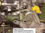
Since the speed is cycling up and down and the set isn't shutting off correctly the next thing to check is the spring on the mechanical governor.
Below is a picture showing which hole in the arm that the heavy green spring needs to be hooked thru at each end.
The picture is with the mechanical governor plate unbolted and tilted down.
You cab peek behind your plate to see which hole the spring is in.
Governor Spring Hole.JPG
 

Lostranger

Member
32
0
6
Location
Marion, NC
Spring is in proper position top and bottom. After I checked, I closed the gap to a little under 1/4". Now it shuts down with switch, at least with cold engine. Engine speed still cycles constantly. No idea how it may run under load with engine warm.

I would love to proceed with getting load to main bus. Weather is mostly cloudy. I'm killing what's left of my battery bank.

Thanks for your help.
 
Last edited:

kloppk

Well-known member
Steel Soldiers Supporter
1,967
3,063
113
Location
Pepperell, Massachusetts
In a pinch you can bypass all the safety systems by installing a jumper wire between S5-5 and chassis ground. This will allow you to close the contactor by using S5.
**** Doing so will prevent the set from opening the contactor due to any fault ****
Proceed at your own risk
 
Top
AdBlock Detected

We get it, advertisements are annoying!

Sure, ad-blocking software does a great job at blocking ads, but it also blocks useful features of our website like our supporting vendors. Their ads help keep Steel Soldiers going. Please consider disabling your ad blockers for the site. Thanks!

I've Disabled AdBlock
No Thanks