• Steel Soldiers now has a few new forums, read more about it at: New Munitions Forums!

  • Microsoft MSN, Live, Hotmail, Outlook email users may not be receiving emails. We are working to resolve this issue. Please add support@steelsoldiers.com to your trusted contacts.

MEP002a - Exhaust Shutter

Speddmon

Blind squirrel rehabiltator
Super Moderator
Steel Soldiers Supporter
4,640
28
38
Location
Cambridge, Ohio
OBC, the "normal running position" I'm referring to is when you have it running along happily at 60 Hz (1800 RPM) output. Like Carl said, from that point, I just remove any load from the set, let it chug along unloaded at 1800 RPM for a minute or so, and shut it down. At the next start-up when it fires off, it will go back to that 60 Hz range all by itself. Mine actually start off a little below that when cold, maybe aroung 55 Hz or so, but as they come up to temp they fall right into 60-61 Hz on the nose.
 
38
0
6
Location
Thumb (MI)
Update.

I ran my 002a this weekend for a 30 minute run-up. Started great in 25 degree weather (no problems). Oil pressure was steady between 35-40psi just prior to shutdown. Shutters did NOT even open.

I did notice that the volt gauge was reading in the yellow which fell from being in the green when first started. Is this an indication of a drain on the batteries? I do disconnect the batteries when not in use as I have noticed a slow drain when setting if the cables are connected. I believe disconnection is recommended if a solargizer is NOT installed.

A quick read of the TM in this area suggests the following:

BATTERIES DO NOT CHARGE.
Step 1. Check battery charging alternator stator (paragraph 8-2).
Replace bad stator.
Step 2. Check battery charging alternator rotor (paragraph 8-2).
Replace bad rotor.
Step 3. Check regulator-rectifier assembly.
Replace bad regulator-rectifier.
Step 4. Check DC control windings in the CVT (paragraph 6-9).
Replace if circuit is open.

Any thoughts?
Could this be a diode problem and if so, can just the diodes be replaced? Available?

thx,

t~
 
Last edited:

Speddmon

Blind squirrel rehabiltator
Super Moderator
Steel Soldiers Supporter
4,640
28
38
Location
Cambridge, Ohio
OBC,

To check your charging system, it is best to have it running and put a voltmeter across the batteries. You should be putting out about 26 1/2 volts give or take. If you are not, then you can use the TM to check the charging system. As far as having a draw on the batteries when the set is off, it could be the capacitor or the voltage regulator going bad. If it is the voltage regulator (DC) they are sealed and cannot be repaired easily, if at all. If it is the external capacitor that is shorted and allowing your draw, that should be easy to replace.

In order to check either of these you would need to take the cover off of the blower wheel at the rear of the engine. Once you have it off, you will see, on the left side, the voltage regulator and a terminal strip mounted right below it. The capacitor in question is right below the terminal strip and has one lead tied into the terminal strip (along with another wire under that particular screw) and the other lead is hooked to the right side mounting screw for the terminal strip (grounding that side of the capacitor). The easiest check I can tell you to make would be to put an amp meter in line with the negative battery terminal with the set OFF. Then loosen and remove that grounded capacitor lead. If the capacitor is bad, your draw on the batteries will be gone, as indicated by the amp meter. If it remains then more than likely the problem is a diode in your voltage regulator and it will need replaced.

The voltage regulators are still available from Southern Automotive Wholesalers in Michigan. But they are not cheap at over $100 each. IIRC they sell through their e-bay store but a call to them wouldn't hurt. Or you could go the used route through Delk's Army Navy Surplus.

If you have any problems or questions let me know, I'll do what I can to help.
 
38
0
6
Location
Thumb (MI)
Speddmon,

OK. I'll run through those tests and give an update. I have a "parts" genset that I can possible get a regulator from. Either way I'll let you know.

Thx!

t~
 

Carl_in_NH

Member
834
7
18
Location
Wilton NH
Don't forget to check the fuse in the fuse holder for the charging circuit first!

It's on the sheet metal cover where the wires come out from the blower wheel area - standard 3AG fuse, 10 AMP - if memory serves.
 

glcaines

Well-known member
Steel Soldiers Supporter
3,843
2,410
113
Location
Hiawassee, Georgia
When I start my MEP-003A, the voltmeter always initially shows in the green for 10 - 15 seconds and then falls down into the yellow. It then slowly creeps back up into the green as the batteries are charged over a period of time. I don't know if this is normal or not, but my charging system seems to keep the batteries charged OK.
 

Grove

New member
24
0
1
Location
MO
The air intake shutter is the black knob located on the air cleaner housing...that is manually operated only.

The exhaust shutters (Shutter Box Assembly) are on the box surrounding the mufflers and has the exhaust pipes exiting through the box.

These units are air cooled, using the fan at the back of the engine...when the shutters are closed the air circulates inside the shutter box and around the housings and exits where it can. When the unit get's warm enough, the shutters open allowing the cool air that is drawn in by the fan to blow directly across the cylinder heads when they get warm and exit through the open shutters to help to cool them. If the shutters didn't open when it starts to get warm, you're soon going to be tripping out the high temp shutdown switch located inside that box which is between the heads. Also, lord forbid, if that switch fails and does not open then you will seize your engine from the heat generated...the shutters have to open when the space inside the box get's warm.

After the first minute of running, even in the coldest temps, the cylinders will be plenty warm enough that that air intake line coming from the shutter box will not be necessary any longer. The air only comes from that box to aid in starting and running until the engine comes up to temperature...once at temp, the hot cylinders will ensure combustion of the fuel, and warm air is no longer needed.

I hope this clears it up some for you...any other questions feel free to ask.
Is the manual air intake shutter something I should be concerned with in regards to running or starting my genset?

Grove
 

Speddmon

Blind squirrel rehabiltator
Super Moderator
Steel Soldiers Supporter
4,640
28
38
Location
Cambridge, Ohio
You can be concerned about it if you want to, one of mine is stuck in the "Normal" position and the other I can freely move from "Normal" to "Cold Weather" position.

Actually, If your glow plugs and manifold heater are working it should not really be necessary at all. It does absolutely no good for a cold start as the air inside the shutter box should be the same temperature as the outside air. The only advantage you have with it is after the set warms up, then you're getting warmer air in the intake. But if you want to get really down and dirty into the physics of it, the colder air is more dense so therefore more O2 present, meaning it would be better to run with it always in the "Normal" position.

Basically, it's up to the operator if you choose to switch it over for cold weather operation.
 
38
0
6
Location
Thumb (MI)
OBC,

To check your charging system, it is best to have it running and put a voltmeter across the batteries. You should be putting out about 26 1/2 volts give or take. If you are not, then you can use the TM to check the charging system. As far as having a draw on the batteries when the set is off, it could be the capacitor or the voltage regulator going bad. If it is the voltage regulator (DC) they are sealed and cannot be repaired easily, if at all. If it is the external capacitor that is shorted and allowing your draw, that should be easy to replace.

In order to check either of these you would need to take the cover off of the blower wheel at the rear of the engine. Once you have it off, you will see, on the left side, the voltage regulator and a terminal strip mounted right below it. The capacitor in question is right below the terminal strip and has one lead tied into the terminal strip (along with another wire under that particular screw) and the other lead is hooked to the right side mounting screw for the terminal strip (grounding that side of the capacitor). The easiest check I can tell you to make would be to put an amp meter in line with the negative battery terminal with the set OFF. Then loosen and remove that grounded capacitor lead. If the capacitor is bad, your draw on the batteries will be gone, as indicated by the amp meter. If it remains then more than likely the problem is a diode in your voltage regulator and it will need replaced.
OK. Warmer weather is here in MI and I finally got around to taking off the back ASK panel as well as the shroud to test.

First, with the set running, I took a voltage reading with a multimeter across the batteries and I got 24.6v.

Second, I have a couple questions about testing the current as you stated Speddmon. You want me to put the black lead to the negative terminal on the battery correct? Where do I put the positive lead from the tester before I disconnect the ground lead on the capacitor? Forgive me for some "dumb" questions?

t~
 

Speddmon

Blind squirrel rehabiltator
Super Moderator
Steel Soldiers Supporter
4,640
28
38
Location
Cambridge, Ohio
Basically, you will want to disconnect the negative battery terminal. Use your multimeter (set for DC amps) to complete the circuit. Black lead attached to the negative post of the battery, and the red lead attached to the negative battery cable terminal. With the set not running, this will show you if you have any draw on your battery. Once you disconnect the grounded lead of the capacitor, if the draw goes away, then you found your draw source.

It's a very crude drawing, but this should help you out some...I hope
 

Attachments

38
0
6
Location
Thumb (MI)
Alright...I just tested as you described and there is a draw of .07 when set on DCA. The draw stays there even when I disconnect the ground wire to the capacitor. The draw stops when I pulled the fuse to the voltage regulator so I assume its the regulator then.

I'll pull the regulator off my other genset and swap this weekend to test. Thx for your help!

t~
 

Speddmon

Blind squirrel rehabiltator
Super Moderator
Steel Soldiers Supporter
4,640
28
38
Location
Cambridge, Ohio
It sure sounds like the regulator to me, now that I know what you tested. I'm curious to know if the other one you have fixes your problem. If it's a good one it should. The fact that you are only getting 24.6 volts running tells me that either your VR is bad or the stator behind the blower is bad, unlikely but not unheard of.
 
38
0
6
Location
Thumb (MI)
Okay.... weather is miserable here in MI. Rainy and cool... go figure for early March eh?!

I managed to open my crated spare 002a yesterday and pull the VR. This was the first time I actually took a GOOD look at this spare unit and I was surprised at what a difference there was between it and my other unit with the ASK kit, cosmetically speaking. The ASK kit unit had little corrosion on anything versus some on "uncovered" set. I also notice more "grime", dirt as well on the open unit.

Anyway... I swapped out the VR and tested the following:

1. Tested for current flow (amps) while off and NO DRAIN - Good News!
2. Tested voltage on batteries while OFF and got a 26.5 - Good News!
3. Tested voltage while running...rReading started out around 26 something and rose steadily and then pegged at 28.5 v - Good News!

TM says the following on test for alternator charging:

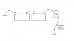
b. Test on Equipment.
(1) Load the batteries with a 12 ohm, 200 watt
resistor (see figure 7-8). Run the set at 60 Hz, 1800
RPM. The charge rate should be between 6.5 and 10
(2) With generator running (60 Hz), disconnect
batteries leaving 12 ohm resistor load in circuit to
generator. The alternator should provide a dc voltage
between 24 and 28.5 volts.

- My Volt meter on the interface panel no longer stays in the yellow but increase and stays in the green - Good News! It looks like it was my VR.

Thanks for everyone's help....this site is awesome!![thumbzup]
 

Carl_in_NH

Member
834
7
18
Location
Wilton NH
Glad to hear you're squared away. As a note of potential interest, this is the third failed 24V charging rectifier / regulator I've heard of in the last month or so. Appears as if it's a common failure.
 
Last edited:

DieselBob

Active member
2,891
13
38
Location
Arnold Maryland
As a note of potential interest, this is the third failed 24V charging rectifier / regulator I've hear of in the last month or so. Appears as if it's a common failure.
I might have to pickup 2 or 3 extra gen sets so I have a spare vr. Now can I convince the boss this is the way to go :mrgreen:

Glad to hear it's fixed.
 

Speddmon

Blind squirrel rehabiltator
Super Moderator
Steel Soldiers Supporter
4,640
28
38
Location
Cambridge, Ohio
OBC,

Glad to hear you got it squared away. Troubleshooting these sets really isn't that big of a deal. The TM will get you there; but the way I had you do it, in my opinion anyway, will get you there a little quicker.

Bob,

Spare parts are always a good idea...LOL. I'm not sure if the EOM even has any of the voltage regulators left or not. They did have some for sale on e-pay a while back, but they were kinda spendy.
 
Top
AdBlock Detected

We get it, advertisements are annoying!

Sure, ad-blocking software does a great job at blocking ads, but it also blocks useful features of our website like our supporting vendors. Their ads help keep Steel Soldiers going. Please consider disabling your ad blockers for the site. Thanks!

I've Disabled AdBlock
No Thanks