• Steel Soldiers now has a few new forums, read more about it at: New Munitions Forums!

  • Microsoft MSN, Live, Hotmail, Outlook email users may not be receiving emails. We are working to resolve this issue. Please add support@steelsoldiers.com to your trusted contacts.


mep004 reads 0 phase to phase 480 phase to ground

peapvp

Well-known member
Steel Soldiers Supporter
1,032
1,055
113
Location
Basehor, KS
Typical A11 failure. It happened so often in the 90's, that the A1 became an automatic return upon failure. You simply turned it in, and got a new one. No one, at least here in Germany, repaired them anymore.
Guy,
I can see why. All these diodes with the white belly are the JAN 1N42xx which have that white glass around them.
I usually replace them with 1N4007 which have higher surge and voltage ratings and they last until doomsday.
The Transistors, the UA723HM and zeners are fine.
The newer SCR’s are also more rugged.
I think I may make a replacement board for the A11 with more modern, more rugged parts.
Otherwise they are fine.

Peter
 
Last edited:

peapvp

Well-known member
Steel Soldiers Supporter
1,032
1,055
113
Location
Basehor, KS
Update:

we had to strip the board another 19 hours for a total of 39 hours of stripping time.

These boards were immersed in silicone conformal bath after population, soldering and cleaning when they where build.

The boards where then hung upside down to cure.

The most buildup of conformal coating is on the solder side from the position of the soldered wire connections and from there up to the middle of the board.

It took an additional 19 hours to strip this area which we had to clear to be able to remove the entire row of JAN 1N42xx diodes with the broken glass bodies before they all fail like the CR22

Note for the interessested diy’ser:

The stripper we use is a highly corrosive commercial stripper.

These Strippers work best at 45C to 50C and with agitation.

This requires a Stainless Steel Batch Stripper machine with stainless steel oscillating nozzles, pumps and plumbing and either a stainless steel or titanium heat element with stainless steel exhaust system and fan.
This would have reduced the stripping time to 2 to 4 hours instead of 40+ hours.
We do not have such a machine as we rarely do this kind of work.
We are a manufacturer not a repair shop specialized in repairing these boards.

However, we can do this kind of work if we have to.

If you want or need to do this at home, please be very careful.

The stripper is highly corrosive to certain plastic, rubber, styrofoam and the chemicals used in silicone conformal coating.
It may attack certain paints and may dissolve some markings or plastic covers on electronic components.
It will normally not damage any components but all carbon based resistors should be checked / replaced after stripping as the stripper can protrude the porous surface of those type resistors.
The fume alone will damage the internal rubber seal in the Amphenol receptacle which should be removed prior to stripping or best replaced to begin with.

Work in a well ventilated area.
Wear Safety goggles, chemical resistant gloves and clothing.
Follow all instructions on bottle of stripper and MSDS.

Stripper is removed with 99.6% isopropyl alcohol and then washed with deionized water and fully dried.

The board is then ready for repair.
 

peapvp

Well-known member
Steel Soldiers Supporter
1,032
1,055
113
Location
Basehor, KS
Update:

Pictures of the stripped board, with some minute conformal coating left in between the soldered wire connection. Also visible, the dried out Rubber Gasket in the Ampheneol Receptacle. The rubber was only exposed to the fumes in the stripper batch since we had the bath closed off air tide. The Rubber expanded and I pulled the loose pieces out. Recommendation is to remove receptacle if you want to use it again and if it is still usable.

All the larger Carbon Type Resistors are 1/4W, 1W and 2W all 5% but deemed to be MIL STD and are High Reliability.
In this case back 40 to 70 years ago that meant, that out of 1000 resistors of that batch of resistors, 0.001% would fail within the first 1000 Hours.

These are all AB (Allen Bradley) Resistors with a 750 V (W.V.) Rating. A relic from the Tube days long gone.

The Metal Film are RN 55 1/8W 1% Resistors with 500 V (W.V.) rating

Capacitors all are good within +/- 1% of their rating with very very low ESR - they have not deteriorated

Next update will be the then replaced components and the re assembly and testing of A11

Note:

The published TM ending in -24P call out as bare PCB 30554-72-2600
This is the newer version of this PCB which means that the VR in this A 11 was replaced at one point.

The schematics in the other TM's show the newer schematic for this PCB

The original 30544-72-2600 (NO NSN available) had 4 more components which have been omitted in the 30544-72-2616


5FEC68DA-60FF-4E25-B6B8-87EB5B5E808D.jpeg
6B1237B3-F149-43D0-8D23-A55ACDC9C8C0.jpeg
068AD449-01A8-46A0-B631-09F99165F056.jpeg
C884BF03-1A83-46B5-AB5B-E47282DE9B2E.jpeg
57BE96B1-CA54-417B-97B0-F5203745FA6F.jpeg
696AA605-A40A-4590-89A6-3325A0FE214E.jpeg
 
Last edited:

Guyfang

Moderator
Staff member
Moderator
15,871
22,096
113
Location
Burgkunstadt, Germany
There is no such thing as an original A11. Every gen set that was ever built, has had more A11's installed in them, then I have teeth left over in my head. Don't get me wrong. The A11 was, relative dependable. But it was a "high" (to me anyway) usage part. If I had a 004, 005 or 006, I would replace the A4 and A5 card, (currently being produced with modern parts) and the A11, if someone made one that was a drop in part. No mods needed. Then the only weak link to these sets would be the Thermal Watt Converter and the S9. Then these sets would run till the second coming.
 

peapvp

Well-known member
Steel Soldiers Supporter
1,032
1,055
113
Location
Basehor, KS
There is no such thing as an original A11. Every gen set that was ever built, has had more A11's installed in them, then I have teeth left over in my head. Don't get me wrong. The A11 was, relative dependable. But it was a "high" (to me anyway) usage part. If I had a 004, 005 or 006, I would replace the A4 and A5 card, (currently being produced with modern parts) and the A11, if someone made one that was a drop in part. No mods needed. Then the only weak link to these sets would be the Thermal Watt Converter and the S9. Then these sets would run till the second coming.
Guy,

i am in the process of doing just that, designing a direct replacement A11.
I am going to take a look at the Thermal Watt Converter as well.
What does it look like with the governor controller for the precise units?

Peter
 

peapvp

Well-known member
Steel Soldiers Supporter
1,032
1,055
113
Location
Basehor, KS
There is no such thing as an original A11. Every gen set that was ever built, has had more A11's installed in them, then I have teeth left over in my head. Don't get me wrong. The A11 was, relative dependable. But it was a "high" (to me anyway) usage part. If I had a 004, 005 or 006, I would replace the A4 and A5 card, (currently being produced with modern parts) and the A11, if someone made one that was a drop in part. No mods needed. Then the only weak link to these sets would be the Thermal Watt Converter and the S9. Then these sets would run till the second coming.
Guy,

two more things:
A) by original I meant the PCB Revision 1.
The PCB I got here is a later revision

B) I have been testing those A11 here in the lab and what I am finding out is:
Capacitor C2’s only purpose is Power Factor Correction when paralleling two units to maintain equal voltage output

That works great, however C2 causes a excessive amount of current draw on T2 when the Genset is operated as standalone unit with a load demand of greater then 90%

the PFC at this point is completely out of whack.
PFC works fine to 75% load as single unit.

Any Voltage sagging will completely through off A11 if C2 has a capacitance greater then 20.5uF

so, you load bank your Genset to 100% with a aging C2 then it is only a matter of time until Transformer T2 is going up in smoke.

Unequall load, like using only one or two legs for 208V/120V will reduce the stability point of the PFC down to 50% of rated power before PFC becomes unstable.

Peter
 

Guyfang

Moderator
Staff member
Moderator
15,871
22,096
113
Location
Burgkunstadt, Germany
Peter,

The MEP Precise units were a rare bird. Very few produced/used. Unless you count the 400 hertz models. THEN, you have a boat load. But, as we all know, 400 hertz is not a high usage machine in the real world. Having said that, The electric governor module was another weak link. We had lots of problems with them, and in the ADA world, we needed good stable power. They were always out of wack, and because they were so easy to get at, and had the two adjustment pots on the front, people just loved to knob dick them.

The documentation was very bad in the beginning, and lots of problems were self induced. Add that to the MPU. It was the first usage of an MPU on a gen set we had ever seen. Everyone thought that you just install it, and its good for the next 500 years. Boy were we dumb. No one EVER looked at the MPU when we had stability/engine speed control problems.

The electric actuator, was, in contrast, the most bomb proof device I ever saw in my life. I never, ever, replaced one. Never. And as long as no one fooled with the linkage, it simply never was a problem. When we first got the MOD, it was a very straight forward installation. The longest part of it was drilling and tapping a hole in the engine bell housing. Later, every engine came with the hole in it.

If you decide to do the Electric Gov, I would bet you never sell a one, in your life. I might be wrong. But the only precise units I have seen in the forum, were 400 hertz unit, with one exception. And it was FMC.
 

peapvp

Well-known member
Steel Soldiers Supporter
1,032
1,055
113
Location
Basehor, KS
Update:

Transformer T2 is installed. C2 is still good, so we leave as is. The new T2 is protected on the primary side with a 3 Amp 3AG inline fuse.
This will prevent T2 from over heating in the future.

The original T2 has a 500 VA rating but the actual power needed is app 150 VA to 200VA under full load.

The replacement T2 has a 250VA rating and will do the job just fine.

The Mil-Std used to derate every part to 50% or 33% which meant you had to oversize every component by 200% to 300%
We have 350VA and 500VA T2 Transformers available, but their sales prices are pretty steep in case someone would like to have more headroom.
The real current draw happen during paralleling when both output voltages are not 100% equal. The higher voltage Genset then dumps a massive current into the lower voltage Genset.
Please see my video from 2013 below, sorry but this video was done with my old old camera at that time 😞

Peter

89BEF812-E730-4543-95E9-3FB75B24E482.jpeg


peapvp

Well-known member
Steel Soldiers Supporter
1,032
1,055
113
Location
Basehor, KS
Update:
I am replacing the 1/2W 1W and 2W resistors.
R4 and R5 are 750 Ohm 2W 5% 0.001% failure
Color Code:
Purple, Green, Brown, Gold, Yellow

can you see the faint traces of the original color bands?
2C5A491E-2E75-47AE-BA3E-81BF2938A5E2.jpeg

first three bands are value, fourth tolerance and fifth failure rate

they came in measuring 862 and 827 Ohm, they got baked pretty well and color bands changed their colors due to heat.

Typical issue with Carbon Resistors when they get old.
 

peapvp

Well-known member
Steel Soldiers Supporter
1,032
1,055
113
Location
Basehor, KS
Update:
After a closer inspection it turned out that 5 of the 1/4 W 1% Carbon Resistors had hairline fractures. All 5 were within 25% of their value.
All other 1/4W 1% carbon resistors and the 1/2 W 1% Carbon Resistor had doubled in Value.
This is a typical thing with any carbon resistor and we replaced all of them with 1/4W 1% Metal Film except for R14 and R20 where we had original parts available in stock from other military equipment

C72C180A-9507-4577-A3EE-C7FACF6E03B9.jpeg
 
Last edited:

peapvp

Well-known member
Steel Soldiers Supporter
1,032
1,055
113
Location
Basehor, KS
Update:

Replaced the 6 Diodes: CR1, CR2, CR3, CR4, CR5, CR6

One thing I noticed on the components which are mounted to heat-sinks is that the original Thermal Joint Compound had completely dried out and provided no more heat transfer.

Some parts of this A11 were manufactured in 1989 week 9:
The Diode Assembly and the VR Board, all other parts were manufactured in the 1970's. So this A11 underwent some maintenance / repair probably in the 90's.

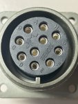
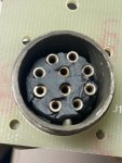
The PCB is fully repaired now except for the Amphenol Receptacle J11. I had ordered a MS3102R18-1SX from Mouser for 25 bucks.
Mouser has the original MS3102R18-1S in stock for 150 Dollars.
I should have checked with Allied Electronics first, they have the original MS3102R18-1S in stock for $ 49.99 (is coming in from Allied today)

The difference between the MS3102R18-1S and the MS3102R18-1SX is the X
without X: machined socket pins
with X: spring loaded socket pins

Those are 18-1

The Mouser MS3102R18-1SX is a Bendix Made in USA, however, the person who assembled those, rotated the insert by app 180 Degrees and now the PIN A is no longer on the side of the connector guide...........

When the Allied Part gets here I can complete the A11 and test it and sent it back.

Note:
I added solder to the PCB traces. This PCB was made the old fashioned way, silk screening the traces, etching, drilling and then tin plating the traces.
This is a single sided PCB without plated through holes.

At this age, the solder pads will come off the PCB during de soldering a component. To prevent further damage to the PCB, as eventually all traces will separate from the fiber glass substrate, I would recommend adding solder to the traces like in the picture below.

I know this doesn't look beautiful or pretty, but we are trying to restore aging electronics. We are not in it trying to win a beauty contest..........


4A3E9695-7D6E-4599-861A-76E6CC048F3E.jpeg
E69E2C5C-E258-408A-8EB4-1F503539DF60.jpeg
41DE2721-C761-4F7D-9562-BA8B4E0E8DCE.jpeg
DDB6572C-FA0C-4B43-BD5F-1BC1BE709B7C.jpeg
DC9F67B4-4A22-4A85-BBD1-1B7C4C84C910.jpeg
3C79D030-10DF-48FC-A5C6-A18B7437EAEF.jpeg
 

Attachments

peapvp

Well-known member
Steel Soldiers Supporter
1,032
1,055
113
Location
Basehor, KS
Update:

The correct J11 just got here. Both are 18-1 left ITT Cannon which is correct, right is Bendix which is going into the trashbin.

F2CF9764-4BD3-450D-B9DF-3E6AF8D659F9.jpeg
 

2Pbfeet

Well-known member
239
410
63
Location
Mt. Hamilton, CA
Update:

Transformer T2 is installed. C2 is still good, so we leave as is. The new T2 is protected on the primary side with a 3 Amp 3AG inline fuse.
This will prevent T2 from over heating in the future.

The original T2 has a 500 VA rating but the actual power needed is app 150 VA to 200VA under full load.

The replacement T2 has a 250VA rating and will do the job just fine.

The Mil-Std used to derate every part to 50% or 33% which meant you had to oversize every component by 200% to 300%
We have 350VA and 500VA T2 Transformers available, but their sales prices are pretty steep in case someone would like to have more headroom.
The real current draw happen during paralleling when both output voltages are not 100% equal. The higher voltage Genset then dumps a massive current into the lower voltage Genset.
Please see my video from 2013 below, sorry but this video was done with my old old camera at that time 😞

Peter

View attachment 877877

@peapvp I enjoyed your YouTube video tutorial, which gets to the heart of why paralleling, and load balancing, multiple generators is difficult. Is part 2 somewhere around?

All the best,

2Pbfeet.
 
Top
AdBlock Detected

We get it, advertisements are annoying!

Sure, ad-blocking software does a great job at blocking ads, but it also blocks useful features of our website like our supporting vendors. Their ads help keep Steel Soldiers going. Please consider disabling your ad blockers for the site. Thanks!

I've Disabled AdBlock
No Thanks