Scoobyshep
Well-known member
- 1,394
- 2,198
- 113
- Location
- Florida
From the video

Sent from my SM-G973U using Tapatalk

Sent from my SM-G973U using Tapatalk
Steel Soldiers now has a few new forums, read more about it at: New Munitions Forums!


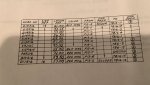
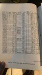
yes it seems like a few at least one of the wires is in the wrong place based on what I was able to find form the manual.You should go on line and look up the complete single phase conversion procedure. If it was done properly there are 3 more small wire connections that need to be put back in their original positions on the back of the reconfiguration board. These other connections would have been moved to make the gages work correctly in the single phase mode. Here are the wires you need to check. Below is the procedure to go TO single phase, so reverse these connections to get back to 3 phase.
View attachment 824612
yes it seems like a few at least one of the wires is in the wrong place based on what I was able to find form the manual.
looks like the wire numbers you referenced above a different for the MEP006A except for the third one. Below is how i think it should be wired.
X7E16A connects to TB6-7
X8E16B connects to TB6-8
X14H16 connects to TB6-1
X15A16 connects to TB6-2 (this one currently in wrong place)
X16H16 connects to TB6-3
X9GP16C connects to TB6-9
X12EG16N connects to TB6-12
X6A16 connects to TB6-6
X12P16N connects to TB6-12
X9J16C connects to TB6-9
Got it switched back to 3 phase 416vFrom the video
Sent from my SM-G973U using Tapatalk
Glad to hear it. Any time ,always happy to helpGot it switched back to 3 phase 416v
thank you for all your help.
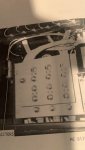
OK, Between Scooby and Ray, if you take good care and check EVERY SINGLE wire on TB6, and get the wires squared away in the control cube, you will be golden. BUT, and you better pay close attention here, cause it happened to me, and a number of my friends at one time or another, the position of the wires on the back side of TB6 have to be right. Sometimes its tight back there. Getting all those cables tight and in place can be a problem. The standoffs for TB6 give you some room to adjust where the wires can be routed. But sometimes when you are securing the TB6 back in place, the wires can move. Or several wires can push another a tiny bit, and then there is a problem.
One of the most impressive light shows I ever saw in my life, happened about 2 feet from my face. We put in a new main gen and tightened up the cables on the TB6. It was a bear to get back onto the standoffs. So we just muscled it into place. One of my guy started up the set, while SP/5 guyfang stood there looking at the output side of the gen set. The main gen got excitation voltage and took off. The sparks and flame shot out at me like a volcano. And the high voltage "scream", is a wonder.
There is not much you can do about it. Its before the CB2 (output contactor) so NOTHING will shut off the output power. If someone is not brave enough to step up and hit the S2 into the off position, the set WILL run until the offending parts melt through.
Another warning is the nuts and studs on the CB6. The studs and nuts are soft metal. You over tighten them, you will be looking for a new TB6. And those baby's have to be tight. Loose connections will cause problems that will drive you batty.
[/QUOT
Thank you greatly for the warning. Will be sure to keep that in mind.
Just found out that one of the load terminals L2 is not outputting any voltage, looks like there might be an issue with main load contactor. Also the vault light indicators and the frequency meter are not working. Reading through the manual now to see if I can figure out what's going on there.
ok will take a look at those items.The fault indicator has a fuse in the panel. Is it good? Then check the C-Plug on the back. Tight? On straight? If all else fais, open the box up and see if the relay is in it.
The A2, (freq converter is in the control cube. Open the control panel door and it in the middle, up top. Its marked A2. Two wires to the left should be AC voltage. Test there to see if you have AC input.
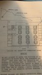
Here is the current configuration of the reconnection board. I suppose I need to shift it up vertically so that the number 4 lines up with the arrow for 240/416 correct?
Dear sir i have one generator MEP806A and i wand to change out suply from 120v to 240/416v . only open 12 screws and shift it up vertically so that the number 4 lines up with the arrow for 240/416?