• Steel Soldiers now has a few new forums, read more about it at: New Munitions Forums!

  • Microsoft MSN, Live, Hotmail, Outlook email users may not be receiving emails. We are working to resolve this issue. Please add support@steelsoldiers.com to your trusted contacts.

Mep806b no power to control panel

Still-In

New member
2
2
3
Location
Wyoming
Howdy yall. As the title suggests, I have a MEP806b here that has 24 volts coming from the battery to the slave. But no power or lights or anything to the control panel or anything behind it in the box. The manuals I have seem to be extremely lacking in this department. Any help would be greatly appreciated as we need this generator up and running asap. TIA
 

Guyfang

Moderator
Staff member
Moderator
17,663
26,260
113
Location
Burgkunstadt, Germany
Is this set new to you? Have you ever seen it run right? What manuals? Did you down load them from the SS forum? What have you checked? Did you look at S17, the emergency off switch? Do you have 24 VDC to one side? If pulled out, to the other side? Is the set complete? Parts missing? We need a little more info.
 

Still-In

New member
2
2
3
Location
Wyoming
So quick update. This set is not new to me. I had it running before it and I got moved to a new location. The set is complete. I just got back in from tinkering around a bit more. I swapped out the batteries just to make sure they are charged and good to go. I definitely have 24v to the slave receptacle. But now when I hook up these batteries and then try to press cb1 in, it will trip. And of course if I try to hook them up with cb1 in, it'll try to melt the cable and terminal. So I think the problem lies somewhere between cb1 and the batteries. The ground is well grounded. All cables are tight and the same goes for the bolts on the slave receptacle. TIA
 

peapvp

Well-known member
Steel Soldiers Supporter
1,199
1,461
113
Location
Basehor, KS
We have two wiring diagrams available in this Forum's TM section for the 805B 806B

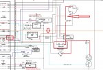
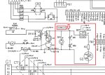
There is a discrepancy as to the labeling of CB1 / F2 and how TB P6-c actually connects, either before or after CB1 / F2

The colored Drawing from MCII shows connection to TB P6-c after CB1

F2 CB1 P6-c Pic 2.jpg


The published TM wiring diagram shows connection to TB P6-c before F2 (directly from Battery +24V)

F2 CB1 P6-c Pic 1.jpg


Note: The plaque wiring diagram(s) inside the side doors overrule any and all published TM's or any other Wiring Diagram
 
Top
AdBlock Detected

We get it, advertisements are annoying!

Sure, ad-blocking software does a great job at blocking ads, but it also blocks useful features of our website like our supporting vendors. Their ads help keep Steel Soldiers going. Please consider disabling your ad blockers for the site. Thanks!

I've Disabled AdBlock
No Thanks