- 179
- 19
- 28
- Location
- Gilroy, CA
Hello, looking for some input on getting this new to me gen set up and running.
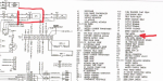
The engine cranks, but fails to start. I've followed the TM trouble shooting as seen by the red arrows:
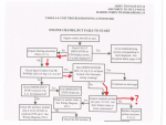
So it seems there is an issue related to the Magnetic Pickup (or MPU as the TM calls it) It appears to be one of the weak links in these units. So I checked it out...
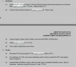
I measured the AC voltage as outlined in the TM, and found it too low, at 0.35V. After adjusting the MPU to the recommended 1.5 turns out, it was still reading too low, at 0.5V. So I screw it in further, to roughly 3/4 turn out and land at 1.55V, just a tad on the high end of a recommended 1-1.5V range. Only problem is that the gen set still won't start, and there is no speed sensor LED illuminating during cranking! Dang! After doing some more research here on SS, some members indicated that it may take as much as 3V to cause the speed sensor to illuminate due to differences in multimeters and the readings they produce. The MPU is now 1/4-1/2 turn out producing 3v and still no LED speed control illumination, and consequently no start.
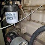
Here is the MPU adjustment procedure for reference. MPU is located on the bell housing, just behind the fuel filler tube.
So at this point I just want to hear the thing run, and know I'm not fighting a fuel issue or other mechanical gremlin. I connect 24V DC from the batteries to the injection pump fuel shutoff, follow the normal startup procedure, clearing faults, and the set roars to life. Instantly. I let it run for a minute, turn to "start" again and excite the field, I'm producing power and it sounds great.
So at least I know its a runner, just not a starter. Haha
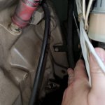
Next I disconnected the J13 junction (the connection at the MPU) and chased the wires back to the P5 junction behind one of the boards above the air filter. The writing all looks good. Pulled off an exterior panel to access the P5 junction to check it for corrosion but is also looks good. Didn't see anything wrong with pin M.
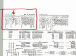
This is where I'm stuck. Still fighting to get the LED speed indicator light to illuminate during cranking, which I believe is preventing the fuel shutoff solenoid from being powered, giving me my "no start"
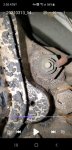
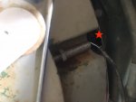
I'm also wondering if I should replace the MPU, (although it CAN supply the correct voltage) considering how far it must be turned in to give the proper voltage range. How exactly does this thing come out? The MPU is so long that the back of the sensor where the wires come out will bottom out against a metal band that wraps the whole flywheel housing. Is there a trick for MPU removal? Access is pretty bad. Red star shows the metal band that causes interference.
Other info on the set:
-It was last tested, ran and cleaned 3/26/08 according to the military. This was at 173hr
-Current hours 345
-Unit has an engine rebuild tag of 2/14/08
-Was previously setup on a ROWPU trailer producing 400hz, I've reset to 208V 60 cycle
-Fuel drained, and refilled
-Oil OK
-Coolant level low
-Emergency kill switch has been bypassed by military with a jumper wire
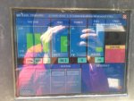
-#28, LED #5 on the backplane module is illuminated red. This is an indicator for low CMOS voltage, which in my research shouldn't cause a no start. Is this correct? Anyone ever replaced the battery?
Any help is appreciated!
The engine cranks, but fails to start. I've followed the TM trouble shooting as seen by the red arrows:
So it seems there is an issue related to the Magnetic Pickup (or MPU as the TM calls it) It appears to be one of the weak links in these units. So I checked it out...
I measured the AC voltage as outlined in the TM, and found it too low, at 0.35V. After adjusting the MPU to the recommended 1.5 turns out, it was still reading too low, at 0.5V. So I screw it in further, to roughly 3/4 turn out and land at 1.55V, just a tad on the high end of a recommended 1-1.5V range. Only problem is that the gen set still won't start, and there is no speed sensor LED illuminating during cranking! Dang! After doing some more research here on SS, some members indicated that it may take as much as 3V to cause the speed sensor to illuminate due to differences in multimeters and the readings they produce. The MPU is now 1/4-1/2 turn out producing 3v and still no LED speed control illumination, and consequently no start.
Here is the MPU adjustment procedure for reference. MPU is located on the bell housing, just behind the fuel filler tube.
So at this point I just want to hear the thing run, and know I'm not fighting a fuel issue or other mechanical gremlin. I connect 24V DC from the batteries to the injection pump fuel shutoff, follow the normal startup procedure, clearing faults, and the set roars to life. Instantly. I let it run for a minute, turn to "start" again and excite the field, I'm producing power and it sounds great.
So at least I know its a runner, just not a starter. Haha
Next I disconnected the J13 junction (the connection at the MPU) and chased the wires back to the P5 junction behind one of the boards above the air filter. The writing all looks good. Pulled off an exterior panel to access the P5 junction to check it for corrosion but is also looks good. Didn't see anything wrong with pin M.
This is where I'm stuck. Still fighting to get the LED speed indicator light to illuminate during cranking, which I believe is preventing the fuel shutoff solenoid from being powered, giving me my "no start"
I'm also wondering if I should replace the MPU, (although it CAN supply the correct voltage) considering how far it must be turned in to give the proper voltage range. How exactly does this thing come out? The MPU is so long that the back of the sensor where the wires come out will bottom out against a metal band that wraps the whole flywheel housing. Is there a trick for MPU removal? Access is pretty bad. Red star shows the metal band that causes interference.
Other info on the set:
-It was last tested, ran and cleaned 3/26/08 according to the military. This was at 173hr
-Current hours 345
-Unit has an engine rebuild tag of 2/14/08
-Was previously setup on a ROWPU trailer producing 400hz, I've reset to 208V 60 cycle
-Fuel drained, and refilled
-Oil OK
-Coolant level low
-Emergency kill switch has been bypassed by military with a jumper wire
-#28, LED #5 on the backplane module is illuminated red. This is an indicator for low CMOS voltage, which in my research shouldn't cause a no start. Is this correct? Anyone ever replaced the battery?
Any help is appreciated!
Attachments
-
 1 MB Views: 24
 -
 166.2 KB Views: 24
 -
 643.4 KB Views: 22
 -
 547.2 KB Views: 24
 -
 70.1 KB Views: 34
 -
 118.6 KB Views: 32