

NATCAD
Active member
- 241
- 50
- 28
- Location
- Port Huron Michigan
Hello gentlemen,
I have a once used HDT MTH35SP (manual here ) without a remote controller and thus no way to start or run the heater.
I've search and found a threat in this forum on rebuilding the battery.
Would anyone be willing to open their controller and take photos of inside so I can make one up?
Would anyone have a spare one to sell?
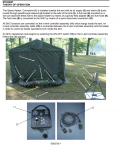
Here is a photo of the unit and a description of the function of controller.


Placing the ON/OFF switch of the in-tent controller in the ON position sends a signal to the power control assembly (1) as well as to the heater control assembly (2) energizing the system. At this point the “heater on/on-hold” advisory light (3) on the in-tent controller illuminates indicating the heater has begun operation. A 12 volt battery pack assembly (4) is used to supply power to the heater control assembly (2) and power control assembly (1) and facilitates burner ignition until the thermoelectric generator (TEG) (5) begins generating power. The power drawn from the battery pack assembly is replaced by the TEG while the heater delivers heat to the shelter. Once power is applied to the system, the heater control assembly (2) sends a signal to the fuel solenoid valve assembly (6), opening the valve and allowing fuel to flow through the sediment strainer (7) to the float assembly (") . Fuel is then pumped in short pulsating bursts by the fuel pump (9) to the burner head assembly (10) where it is vaporized. The heater control assembly controls all electrical functions, including system startup, shutdown, and safety checks. It includes temperature and tilt sensors and the control circuit. The control circuit analyzes information from the sensors to maintain the optimum firing rate for the heater. To maintain the firing rate, it controls the rates of fuel and air flow, and continuously monitors the in-tent controller assembly settings to verify that the desired settings are reached. The control system also controls system startup and shutdown, and monitors the heater safety systems. If a fault is detected, it immediately begins the shutdown procedure and signals the operator that a fault has occurred. Once fuel enters the burner assembly (10), power is drawn from the battery pack (4), fed to the ignition pack (11), and applied to the glow plug (12) igniting the fuel. Cold air is drawn in through the combustion air inlet (13) and heated with the produced heat used to power the thermoelectric generator (5). The TEG converts heat into electricity which is used to recharge the battery pack. When the battery pack is charging, the “battery charging” advisory light (14) on the in-tent controller assembly illuminates. The heater continues to run as the battery pack recharges. When the battery pack (4) is fully recharged, the “battery charged” advisory light (15) on the in-tent controller assembly illuminates and the “battery charging” light (14) extinguishes. At this point, the heated air blower assembly (16) is engaged and cold air is drawn from the shelter through the breathable air inlet (17) and forced through the heat exchanger (1 at the outlet end of the heater. The shelter air is heated and forced out the air return duct (19) into the shelter as heated air. As heated air is supplied to the shelter, the temperature inside the shelter rises. This temperature is monitored by a sensor (20) on the in-tent controller assembly. When the shelter temperature reaches the value set on the “lower/higher” control (21) of the in-tent controller assembly, a signal is sent to the heater, and the burner assembly (10) is shut down. Air continues to circulate through the shelter via the heated air blower assembly (16) and the “At Setpoint” advisory light (22) illuminates. Once the temperature inside the shelter drops below the set point, the burner assembly (10) ignites and supplies more heated air to the shelter. Heater operation is terminated by switching the ON/OFF switch (23) on the in-tent controller to the OFF position. Power is no longer applied to the glow plug (12) and burner ignition terminated. The fuel solenoid valve (6) is closed and all fuel flow to the burner assembly (10) ceases. When all advisory lights are extinguished, the heater is shut down and can be moved or left in place for another operational cycle.
. Fuel is then pumped in short pulsating bursts by the fuel pump (9) to the burner head assembly (10) where it is vaporized. The heater control assembly controls all electrical functions, including system startup, shutdown, and safety checks. It includes temperature and tilt sensors and the control circuit. The control circuit analyzes information from the sensors to maintain the optimum firing rate for the heater. To maintain the firing rate, it controls the rates of fuel and air flow, and continuously monitors the in-tent controller assembly settings to verify that the desired settings are reached. The control system also controls system startup and shutdown, and monitors the heater safety systems. If a fault is detected, it immediately begins the shutdown procedure and signals the operator that a fault has occurred. Once fuel enters the burner assembly (10), power is drawn from the battery pack (4), fed to the ignition pack (11), and applied to the glow plug (12) igniting the fuel. Cold air is drawn in through the combustion air inlet (13) and heated with the produced heat used to power the thermoelectric generator (5). The TEG converts heat into electricity which is used to recharge the battery pack. When the battery pack is charging, the “battery charging” advisory light (14) on the in-tent controller assembly illuminates. The heater continues to run as the battery pack recharges. When the battery pack (4) is fully recharged, the “battery charged” advisory light (15) on the in-tent controller assembly illuminates and the “battery charging” light (14) extinguishes. At this point, the heated air blower assembly (16) is engaged and cold air is drawn from the shelter through the breathable air inlet (17) and forced through the heat exchanger (1 at the outlet end of the heater. The shelter air is heated and forced out the air return duct (19) into the shelter as heated air. As heated air is supplied to the shelter, the temperature inside the shelter rises. This temperature is monitored by a sensor (20) on the in-tent controller assembly. When the shelter temperature reaches the value set on the “lower/higher” control (21) of the in-tent controller assembly, a signal is sent to the heater, and the burner assembly (10) is shut down. Air continues to circulate through the shelter via the heated air blower assembly (16) and the “At Setpoint” advisory light (22) illuminates. Once the temperature inside the shelter drops below the set point, the burner assembly (10) ignites and supplies more heated air to the shelter. Heater operation is terminated by switching the ON/OFF switch (23) on the in-tent controller to the OFF position. Power is no longer applied to the glow plug (12) and burner ignition terminated. The fuel solenoid valve (6) is closed and all fuel flow to the burner assembly (10) ceases. When all advisory lights are extinguished, the heater is shut down and can be moved or left in place for another operational cycle.
I have a once used HDT MTH35SP (manual here ) without a remote controller and thus no way to start or run the heater.
I've search and found a threat in this forum on rebuilding the battery.
Would anyone be willing to open their controller and take photos of inside so I can make one up?
Would anyone have a spare one to sell?
Here is a photo of the unit and a description of the function of controller.
Placing the ON/OFF switch of the in-tent controller in the ON position sends a signal to the power control assembly (1) as well as to the heater control assembly (2) energizing the system. At this point the “heater on/on-hold” advisory light (3) on the in-tent controller illuminates indicating the heater has begun operation. A 12 volt battery pack assembly (4) is used to supply power to the heater control assembly (2) and power control assembly (1) and facilitates burner ignition until the thermoelectric generator (TEG) (5) begins generating power. The power drawn from the battery pack assembly is replaced by the TEG while the heater delivers heat to the shelter. Once power is applied to the system, the heater control assembly (2) sends a signal to the fuel solenoid valve assembly (6), opening the valve and allowing fuel to flow through the sediment strainer (7) to the float assembly (
Attachments
-
 792.6 KB Views: 4
