• Steel Soldiers now has a few new forums, read more about it at: New Munitions Forums!

  • Microsoft MSN, Live, Hotmail, Outlook email users may not be receiving emails. We are working to resolve this issue. Please add support@steelsoldiers.com to your trusted contacts.


Modifying the MEP-002A and MEP-003A generators SX460 AVR

rustystud

Well-known member
9,071
2,388
113
Location
Woodinville, Washington
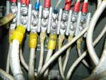
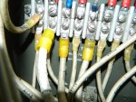
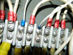
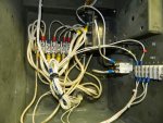
017.jpg018.jpg020.jpg002.jpgView attachment Scan0007.pdf This is the finished reconnection box. The diagram is how I connect the main generator cables to the TB2 buss bar. This is a "double Delta" configuration allowing the maximum use of the generators potential. To avoid confusion I used the actual cable numbers in the diagram instead of "T1 T2 T3 etc" . Later I will show how I modified the control box. The wires I used going out to the control box could have been anyone I chose it to be. I did choose to use the same wires for the field as the original. There on the side of the box is TB3 where the field wires are. P60G16 connects to P60D16 . This wire goes into the control box and connects to TB5 and wire P60A16 which goes to K1 (A1) terminal #7 . I then supply a jumper wire from this junction to the SW460 field terminal #F2 (positive) . The other wire is the field ground which ends up going to terminal #F1 on the SW460 regulator. You can use whatever wire you choose. There are plenty to use ! Again I just use P59 as it's the same field wire in the schematics . Just a note for everyone. The first 3 numbers and letters are the most important in following the schematics. The P59 wire will change it's next letter depending on it's location but it is still the same wire. So the P60A, P60G, P60D are all the same wire. I chose wires X12, X14 to be my ammeter wires for L3 and X40, X22 to be the ammeter wires for L1. Wire #17 is my voltmeter wire for L3 and X15 is my voltmeter wire for L1.
That's basically all there is to it for the reconnection box.
I should mention that on TB2 there are 3 jumpers connecting #1 and 2 then 3 and 4 then 5 and 6 .
After doing this you will have a single phase 120/240 volt generator without all the needless garbage.
 

Chainbreaker

Well-known member
1,748
1,834
113
Location
Oregon
Nice work, looks very tidy in there! This will be VERY HELPFUL when I do decide to tackle the SX460 AVR implementation on one of my MEP-002a units. I look forward to seeing your control box modification portion documentation/pic's.

My only suggestion would be to add/edit the "SX460 AVR" to your thread title so others quickly spot what this modification is intended to accomplish. Also it might make it easier to locate later on when doing searches for information using this particular voltage regulator.
 

rustystud

Well-known member
9,071
2,388
113
Location
Woodinville, Washington
My only suggestion would be to add/edit the "SX460 AVR" to your thread title so others quickly spot what this modification is intended to accomplish. Also it might make it easier to locate later on when doing searches for information using this particular voltage regulator.[/QUOTE]

That makes good sense chainbreaker. I'll do it.
 

rustystud

Well-known member
9,071
2,388
113
Location
Woodinville, Washington
Rusty will you be putting this modification into one thread when complete? I have an 002 that I would like to do this to. Thanks metalworker393.
That's what I was going for here. I need to finish my control box conversion before I post all the pictures and diagrams. I finished my one MEP-002A but I didn't document it enough to make any sense. Now with my MEP-003A I'm trying to do a better job. I also need the gauge conversion kits from JimC. Since I eliminated all the transformers and transducers from the box.
 

dependable

Well-known member
1,720
187
63
Location
Tisbury, Massachusetts
Someone is discussing similar conversion over on the Stak. Consensus there is one might need to battery flash after conversion, but they are using a different AVR. How is yours set up? Does it still field flash with master switch?
 

Triple Jim

Well-known member
1,373
277
83
Location
North Carolina
Flight Systems says their regulator doesn't need the exciter field to be flashed to get output. There is enough residual magnetism to get things going without flashing.
 

rustystud

Well-known member
9,071
2,388
113
Location
Woodinville, Washington
Flight Systems says their regulator doesn't need the exciter field to be flashed to get output. There is enough residual magnetism to get things going without flashing.
"Flight Systems" still need 5 volts to start-up. The Chinese knock-off's need 11 volts. I tried not using any "flashing" circuit but my MEP-002A needs it for some reason. It just does not hold a charge. Even just after shutting down. So that was why it was such a pain for me. I had to keep the flashing circuit installed and I had to come up with a fix for the overvoltage the circuit breaker was getting from the flash circuit. That was the reason for the 50 ohm resistor. Without that resistor the breaker was getting 46 amps through it. It is the one rated 7.5 amps.
At this time I'm also converting my MEP-016D generator. I have totally gutted the control box, and will be installing a Chinese "SW460" AVR. I will also be installing a two "D" cell battery holder for "flashing" the exciter with. Just install a "momentary on" switch and call it good.
 
Last edited:

Triple Jim

Well-known member
1,373
277
83
Location
North Carolina
OK thanks Rusty, I'll stop spreading their information then. You probably know... the original flashing circuit used a similar resistor, which is on the diode board in the box under the output lugs.
 

rustystud

Well-known member
9,071
2,388
113
Location
Woodinville, Washington
OK thanks Rusty, I'll stop spreading their information then. You probably know... the original flashing circuit used a similar resistor, which is on the diode board in the box under the output lugs.
That's what got me looking at the resistor in the first place. I just could not figure out why there was so much voltage going through that stupid switch! Then after looking at that diode bridge I saw the heavy duty resistor and the "light" came on ! Since the "flashing" circuit backfeeds 24 volts straight to the exciter field (and through the master switch) they needed to drop that voltage down to something more manageable.
 
Last edited:

vmccutcheon

New member
8
0
0
Location
McDonough GA
I just purchased two mep-003a's on a trailer as a power plant. The inspection stated they had to jump them off-one stayed running and the other one stalled out. Upon pick up, one had power to prime and the panel lights came on, the other one just dead no power. I got them home and replaced all four 6tl batteries to new. I installed them properly. Now I have no power to the panel lights, priming or glow plugs?? I cycled the push pull switches next the master switch. NOTHING. What am I missing?
 

rustystud

Well-known member
9,071
2,388
113
Location
Woodinville, Washington
I just purchased two mep-003a's on a trailer as a power plant. The inspection stated they had to jump them off-one stayed running and the other one stalled out. Upon pick up, one had power to prime and the panel lights came on, the other one just dead no power. I got them home and replaced all four 6tl batteries to new. I installed them properly. Now I have no power to the panel lights, priming or glow plugs?? I cycled the push pull switches next the master switch. NOTHING. What am I missing?
Make sure the circuit breaker is pushed in. This feeds the master switch.
 

herbertv2

New member
34
0
0
Location
Madera/pa
p67 and p60 are the wires that go to the field right? they are the only 16ga wires that go back to the generator with the 8ga T1-12 wires?
 
Top
AdBlock Detected

We get it, advertisements are annoying!

Sure, ad-blocking software does a great job at blocking ads, but it also blocks useful features of our website like our supporting vendors. Their ads help keep Steel Soldiers going. Please consider disabling your ad blockers for the site. Thanks!

I've Disabled AdBlock
No Thanks