nk14zp
Active member
- 2,636
- 19
- 38
- Location
- Columbia Falls Maine
You can use 4" schd 20 pvc.
Attachments
-
 94.7 KB Views: 74
Steel Soldiers now has a few new forums, read more about it at: New Munitions Forums!


....not with a good shifter boot.... or one not so new but sealed air-tight and firmly strapped in place...!................ remember that the transmission has no seal on the input shaft and thus it will leak out a lot of air and might push some oil with it. ...........................
What did you end up using for a regulator? And would you mind posting some details about what you did on your truck, as far as fording kits go?Let's be realistic here.... what should we expect as a normal" maximum? 50 inches of water? That is having the transmission tunnel already under water, running on 43" tires. The internal pressure needed at axle height or inside the diffs to compensate for this is little over 1psi, not more! 0.5psi for tranny and engine as well as MC...!
I don't think that either fuel tank or air governor or air-pack operation & venting would be affected by such a low "backpressure" of 1 - max2psi, considering that it would be temporary only.
The main problem for me was finding a press. regulator for such a low range and to be sensitive enough to give consistent values, once adjusted. In this sense the original regulator which comes with the OEM fording kit resulted pretty much unreliable, besides other problems...!
G.
Will try to find the specs for that reg. and upload some pics too.What did you end up using for a regulator? And would you mind posting some details about what you did on your truck, as far as fording kits go?
Cranetruck posted something in another thread about an amphibious XMsomethingorother with a multifuel engine and that's exactly what they did.I'm wondering if I should weld in a wye for my crank case breather to dump into the Exhaust system.
Here we go: see the precision regulator SMC IR1010 here http://www.smcworld.com/2008/e/webcatalog/docs/frl/frregulator/IR.pdf#page=1What did you end up using for a regulator? And would you mind posting some details about what you did on your truck, as far as fording kits go?
Will try to find the specs for that reg. and upload some pics too.
G.
")
jesusgatos said:Check out this video. Looks like some kind of promotional video made by/for the military, promoting the early deuces. **** yeah! I love these old trucks.
YouTube - m35a2 deuce under water
military fording kit
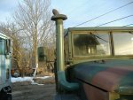
This is what the military's fording kit looks like:

As you can see, there's a snorkel that extends the air intake for the engine up to the height of the exhaust stack. The crankcase vent (slobber-tube) is also routed up to the same height, right alongside the exhaust stack and the snorkel. Finally, the air compressor air intake is connected to a pre-existing fitting on the engine's air filter housing. This is all accomplished with flexible hoses.
It's important to note that these fording kits were not intended to be permanently installed. Or rather, prior to fording, the operators were expected to spend a few minutes preparing the vehicle for deep-water fording.
The slobber-tube could not be left routed up above the engine because it would collect oil and gunk, so had to be re-routed from under the vehicle up to the fording position prior to deep-water fording.
There is a drain-plug for the bellhousing (normally open) which is threaded into a drain-plug keeper right next to the drain hole. Prior to fording the operator would need to climb under the vehicle to remove and install the bellhousing plug.
If the operator expected to spend an extended amount of time driving through deep water, the fan belts were also supposed to be loosened.
The fording kit also included a mini-regulator, an air-switch and lines/fittings to pressurize the bellhousing and the transmission, but interestingly, did nothing to extend many of the other check-valve breathers used all over the vehicles (axles, transfer-case, etc.). Probably because the after-fording maintenance includes re-packing all of the axle-bearings and inspecting/changing all the fluids.
improving on the military's fording kit
I read everything I could find about how the military fording kits worked, and decided that I would like to build a fording kit that I can leave hooked-up all the time. When it's time to get wet, I don't want to have to do anything more than flip a switch and put on my scuba-gear. Not that I'm planning on doing this on a regular basis, but would rather be prepared, and I just can't resist geeking-out on this stuff.
engine intake
Instead of using flexible tubing, I'm going to have a mandrel-bent snorkle made (90-degree bend backwards & angled 45-degrees up, to a 45-degree bend upwards to vertical, to a section of straight pipe that will be capped with a Sy-Klone Series 9000 pre-filter. These centrifugal pre-filters don't have anything to do with fording kits specifically, but are pretty awesome in their own right. They're used on a lot of heavy equipment (agricultural, mining, etc.) and are sold by Cat as a factory accessory. Took that as a pretty solid endorsement.
Not quite sure how tall I'm going to make the snorkle yet, but I want to get the pre-filter up above the windshield so the intake doesn't block any more of my field of vision than it needs to. mudguppy suggested a good source for cheap pre-bent mandrel tubing (here's a direct link).
crankcase vent
So I was thinking about dumping the slobber-tube into the exhaust, kind of like the crankcase evacuation kits that Moroso sells. But then I found these crankcase filters made by Racor/Parker. cranetruck had already done this. Really liked the idea of installing a filter and then permanently routing the crankcase vent to the engine intake, so I ordered a Racor ccv4500 unit.
cranetruck also posted some interesting info about the m656/xm757 trucks, which were amphibious vehicles that were equipped with the same multifuel engines that these M35A2's use. And it just so happened that cranetruck had an extra one of these valves laying around. When I expressed interest in it, he agreed to sell it to me for a very reasonable price. Acquired this out of curiosity more than anything else, but am planning on installing it in addition to the Racor CCV unit.
cranetruck said:Jesse, read about the m656/xm757 trucks, they were designed to swim/ford with a minimum of preparations. They also feature the multifuel engine.
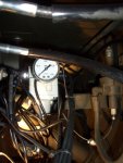
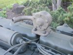
A valve on top of the rocker covers (visible in image #1) makes it possible to pressurize the engine and the blowby gases are normally going out the exhaust (plumbing shown in image #2). No check valve here, the exhaust flow creates enough under pressure to keep fumes going in the right direction.
air compressor
The air-compressor intake has already been re-routed to the engine's air filter housing, as per the military fording kit instructions. But the interesting thing about this is that it draws unfiltered air. No reason for this that I can see, and the way it's plumbed into the air filter housing makes it more difficult to service the air filter. So I'm going to plug that hole and tap into the top half of the air filter housing, which will allow the air compressor to draw filtered air and will also make servicing the air filter easier.
fan
Not sure what I'm going to do about this, if anything. Would like to install some type of fan-clutch anyway, and am wondering if I might be able to adapt something like the on/off clutches that are used on air-compressors. A thermally-operated fan-clutch might even do the trick if the water is able to make contact and cool it. Could also rig-up some type of linear actuators to loosen the fan-belts. Not a high priority in any case, but I would like to discuss fan clutches in general if anybody has any suggestions. The direct-mounted fan on these engines has got to be quite a drag.
cranetruck shared some more helpful info about amphibious vehicles:
cranetruck said:Probably a good idea. The m656 8x8 series designed to swim, have the fan on separate belts, designed to give/stop when subjected to the water. The generator belts will not slip, allowing it to generate power for bilge pumps etc while under water. The water pump is not effected, it runs on the same belts as the generator.
bellhousing drain-hole
Going to replace the drain-plug with some type of cable or air-operated ball-valve that I can open/close from the driveer's seat. Maybe something like this?
front steering knuckles
Noticed that there are two 1/4" NPT allen-plugs in each steering knuckle, and that got me to thinking about pressurizing the knuckles. Inspecting//re-packing the wheel-bearings after fording is suggested after fording water deeper than 18". That's not a particularly fun job, and and that's not a whole lot of water either. I had already replaced the stock knuckle boots with one-piece silicone boots, and I was curious to see what would happen if I pressurized them to 2-3psi. So I replaced one of the 1/4" NPT allen-plugs with a schrader valve, and then used a bike pump to see if the knuckle could hold any pressure. But the silicone boot blew up like a balloon right away, and I hadn't even use enough air pressure to register on the gauge I was using. If I put any more pressure into the knuckle, it was just going to push the boot out into the steering stop.

pressure regulator, manifold & vents / pressure-line
The transmission, bellhousing, transfercase, differentials, brake system, and air compressor governor vents will all be tied into a common vent / pressure system. The fuel system needs to be vented / pressurized separately, as specified in this service bulletin. Not sure how I'll isolate the fuel system (just haven't thought about it yet).
Thinking that I'll run individual 1/4" air-pressure / vent lines to some type of manifold, this 8-port manifold with a main on (pressure) / off (vent) valve, and then a larger common vent line that will be capped with some type of free-flowing filter. Probably mount the manifold and regulator outside the cab (somewhere on the firewall?), then just run the air supply and on/off valve in the cab another air-shift transfer-case switch mounted somewhere on/in/below the dash. That will allow me to run separate lines to everything, while only needing to put one new airline through the firewall (main air supply to the manifold).
Going to install valves at the manifold that will allow me to cut-off air to any of the individual air-pressure / vent lines like readyman did on his deuce. Just an extra precaution, so that in case there's a failure somewhere I will be able to cut off that part of the system.
Was looking at these regulators (highlighted in yellow) is a good choice for this application. It's adjustable from 0-25psi and is non-relieving, which sounds important, since it'll be tied into the main air supply (don't want to bleed off air). But gringeltaube and jwaller both stressed how important it is to select a regulator that is capable of regulating the low-low pressure that we want to be using (2-3psi).
gringeltaube said:The main problem for me was finding a press. regulator for such a low range and to be sensitive enough to give consistent values, once adjusted. In this sense the original regulator which comes with the OEM fording kit resulted pretty much unreliable, besides other problems...!gringeltaube then shared some info with us about the fording kit he built., and the pressure regulator that he chose to use.jwaller said:I believe the std pressure regulator in the original kits was set at 2 psi. remember that the transmission has no seal on the input shaft and thus it will leak out a lot of air and might push some oil with it. I know bjorn has posted a lot about this. and finding a regulator that works with 120psi input and 2psi output is hard. esp when the input air press is constantly changing as it is bled off and builds up.
Another thing I've been mulling over is the idea of installing some type of Tee (or Y) junction where each of the air-pressure / vent lines terminates at the place where it's connected to whatever's being vented. The thing I'm thinking about is that it seems like it might be a good idea to have an easy way to blow-out the lines. Seems to me that with such long vent lines, especially the ones that will run long horizontal stretches, that it's pretty likely the lines will accumulate some gunk and might be prone to clogging. But if I installed valves that I could open/close right where they end (at whatever's being vented), then I could open-up the mini-regulator to let more pressure blow through the lines and clean out anything that might have been accumulating in there. Good idea? Bad idea? Got any better ideas? Open to input here. Help me think this through.gringeltaube said:Here we go: see the precision regulator SMC IR1010 here http://www.smcworld.com/2008/e/webcatalog/docs/frl/frregulator/IR.pdf#page=1
I choose that model over the IR1000 for a higher flow rate in case of leak. It still works pretty accurate at 2psi.
All the tubing is 1/4" nylon. Fittings for all vent ports (1/8"NPT) are std. one-touch connecting, swivel-type elbows.
Even if it doesn't come that way from factory I preferred to also hook up all 3 axle housings plus the TC to the same system. Since the low pressure circuit stays open to atmospheric pressure by default no pressure build-up issues should occur...
Sometimes I think separate circuits at corresponding different settings would be a much better solution..... , maybe one day, for the #1A perfect Deuce...!
Might also tie the remote reservoir for the brake system in to a separate mini-regulator, so I can pressure-bleed the brakes using the onboard air compressor.
Haven't decided what type of lines and fitting to use for all this stuff yet. I asked here and Keith_J suggested Polyethylene. Kinda thinking about using the push-lock airlines and fittings. They're expensive, but am going to be using that stuff for all the air lines anyway and using common parts seems like a good idea.
links
Here are a bunch of links to fording-related threads on steelsoldiers, where I got a lot of this info. Clipped these links from the index, where you can find links to all the content within this thread and a lot more related info, all organized by topic.
- more questions and ideas related to fording kits (steelsoldiers.com)
- Fording Kit Update (steelsoldiers.com)
- Fording Kit Instalation (steelsoldiers.com)
- Fording Thought (steelsoldiers.com)
- Axle Vents: Clean? Replace? Relocate? OTHER vents? (steelsoldiers.com)
- Axel Vent Mod, 2.5 ton Rockwells (steelsoldiers.com)
You are welcome.Hey, thanks again for hooking me up with that valve Bjorn. Installed it on the new LDS engine today, and will probably end up taking it off to clean it up a bit, but it's finally all starting to come together.
Oh I know. Just haven't gotten that far yet.You are welcome.
To do any good, you also need pressurization for it, about 3 psi...