• Steel Soldiers now has a few new forums, read more about it at: New Munitions Forums!

  • Microsoft MSN, Live, Hotmail, Outlook email users may not be receiving emails. We are working to resolve this issue. Please add support@steelsoldiers.com to your trusted contacts.

My 4L80E trouble codes

Mogman

Moderator
Staff member
Moderator
Steel Soldiers Supporter
6,074
8,506
113
Location
Papalote, TX
"Engine RPM" voltage test on the J1 spec is 0.3 V idle, 349A. I got 0.003 V. Actual RPM (the mechanical turning) is fine. 800 idle. It appears even if I manage to get the bolts off there isn't enough room to pull the sensor back to remove, see picture.
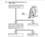
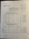
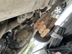
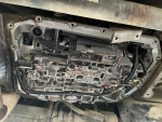
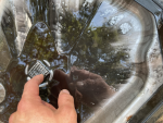
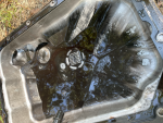
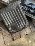
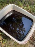
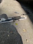
How many ohms does the speed sensor test to (disconnected)?
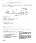
are you using AC or DC scales, you do not have a code 71 so I am curious why you are looking at it.
 

Mogman

Moderator
Staff member
Moderator
Steel Soldiers Supporter
6,074
8,506
113
Location
Papalote, TX
Can you tell me what page the voltage is listed on, I can't find it at first glance.
 

taskunitbruiser

Active member
106
51
28
Location
Alabama
This morning I tried to probe, but then just unplugged the TPS harness. Three wires. 1 wire 0V, 1 wire 0.10 V, 1 wire 0.12 V. Glow plug disconnected, switch in RUN, engine off. So I have bad wiring, but not so bad it can still have some voltage??

Let me check again to make sure I am not off by an order of magnitude. I was expecting one to be 5V though.
 

Mogman

Moderator
Staff member
Moderator
Steel Soldiers Supporter
6,074
8,506
113
Location
Papalote, TX
This morning I tried to probe, but then just unplugged the TPS harness. Three wires. 1 wire 0V, 1 wire 0.10 V, 1 wire 0.12 V. Glow plug disconnected, switch in RUN, engine off. So I have bad wiring, but not so bad it can still have some voltage??

Let me check again to make sure I am not off by an order of magnitude. I was expecting one to be 5V though.
Yes one should be 5V
There may be connections in between that plug and the TCM box because the wire at the TPS is marked C and at the TCM connctor is marked A so the next step would be to back up to the TCM box connector and see if you have 5V on pin d, wire 350A, if you do then start looking for a problem between the TCM and the TPS connector.
If you have 5V at pin d then make sure to re-check at the TPS connector as you may have disturbed the problem when checking at the TCM.
If you do not have 5V at pin d then back up to C4 on the TCM itself.

This is all assuming you have good power to the TCM, can read codes etc.
 

Attachments

taskunitbruiser

Active member
106
51
28
Location
Alabama
Yes one should be 5V
There may be connections in between that plug and the TCM box because the wire at the TPS is marked C and at the TCM connctor is marked A so the next step would be to back up to the TCM box connector and see if you have 5V on pin d, wire 350A, if you do then start looking for a problem between the TCM and the TPS connector.
If you have 5V at pin d then make sure to re-check at the TPS connector as you may have disturbed the problem when checking at the TCM.
If you do not have 5V at pin d then back up to C4 on the TCM itself.

This is all assuming you have good power to the TCM, can read codes etc.
I can read codes and TCM has power. I rechecked voltage again with lever ENG STOP and RUN. ENG STOP is giving ~0.05 V for two wires and now ~0.18 V when in RUN. Other wire is zero every time and checks out for continuity to ground. Other two are "OL" open circuit when continuity tested to ground.
 
Last edited:

taskunitbruiser

Active member
106
51
28
Location
Alabama
If you get all the way back to C4 and still no voltage the TCM is bad.:cry:
I checked voltage from d to c, p, and the rear seat base where some paint was chipped off. All give around ~0.14 V. No 5!!! ah

I am confused if this means my TCM is bad or I have a bad wire between the end of J1 plug and the batteries? I do not get an error 51 "TCM bad", but that would make things too easy if it is bad.

Also the truck is the same useless thing if I disconnect the J1 and try to drive it in manual.
 

Mogman

Moderator
Staff member
Moderator
Steel Soldiers Supporter
6,074
8,506
113
Location
Papalote, TX
If you are getting 12V to pin J and C on the cannon plug and ground is good to wire 599 then the 5v reference in the TCM is Kaput
This would also explain the problem you are seeing on the engine speed sensor as the same 5V reference is used for the TPS, ESS and TTS (trans temp)
 

Mogman

Moderator
Staff member
Moderator
Steel Soldiers Supporter
6,074
8,506
113
Location
Papalote, TX
The TCM probably does not monitor the 5V reference output for a TCM bad indicator
 

Mogman

Moderator
Staff member
Moderator
Steel Soldiers Supporter
6,074
8,506
113
Location
Papalote, TX
I see the diagram with C4 on it. Is this the actual TCM, not either side of the J1 plug, and thus require me to remove the seat to access?
Yes, you should make sure the problem is not between J1 and the TCM.
Actually by now you should have checked/re-seated those connectors.
 

Mogman

Moderator
Staff member
Moderator
Steel Soldiers Supporter
6,074
8,506
113
Location
Papalote, TX
The box the TCM is in is not know for it great ability to keep out moisture/water
 

taskunitbruiser

Active member
106
51
28
Location
Alabama
Ok, got the pan off. A member here confirmed I did need to take off the crossmember as did the TM when I checked that. The TM said remove the drain plug too though (there is not one [maybe 3L80?]). Supporting the transfer case with the floor jack.

Only metal dust on the magnet. Not seeing anything worrisome other than the fluid color and dirty filter, however I do not have much experience here.

What do you guys think? I have already ordered a new filter.
 

Attachments

Top
AdBlock Detected

We get it, advertisements are annoying!

Sure, ad-blocking software does a great job at blocking ads, but it also blocks useful features of our website like our supporting vendors. Their ads help keep Steel Soldiers going. Please consider disabling your ad blockers for the site. Thanks!

I've Disabled AdBlock
No Thanks