ETN550
New member
- 457
- 9
- 0
- Location
- Knoxville, TN
The info below is my opinion so please do not be offended if you do not agree, and your sets may be different. And feel free to interject any comments or corrections. I'm hoping this entry will start some discussion.
I recently have got three of these sets up and running and all were similar in nature.
There are three electrical systems on this unit that are totally separate from each other.
The generator controls are completely inside the box and have no connection with any engine mounted or frame mounted wiring.
The starting circuit is via the slave connection and only goes to the starter. The engine's alternator circuit does not back feed the slave plug to recharge whatever battery is connected to start it. May as well unplug the slave as soon as it is running.
The engines start quite well on 12VDC at the slave as long as the decomp lever is used. The starter solenoid pulls in fine and the starter motor gets good speed if the decomp lever is used.
The engine alternator coil windings put out 50+ volts to the rectifier which is not a regulator. So 50+ volts DC is sent to the fuel tank float switch.
The float switch is rated for 24VDC and the switch is actually a switch / relay combination. So the 24VDC relay coil sees unregulated 50+ VDC. I do not like this.
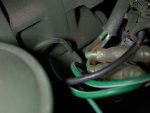
If the float switch decides it is time to activate the pump then the 50+VDC is passed to an unknown component in series. The component is a mystery to me. I have pics below. It is two wire, not labeled as to wire + or - and it has an adjusting screw on it and what appears to be a flat metal base (heat sink?) I put an ohm meter across it and it behaves like a capacitor in that the meter current charges it and the meter reading changes then when the leads are reversed the reading is negative and double and the meter reading changes back. (As though the meter current used in the ohm mode is charging and discharging the device. It says Texas instruments Klixon on it. I wonder if they are just trying to provide enough resistance or regulation to match the alternator coil to the fuel pump since rpm is constant and the pump is the only device on the alternator.
Anyway from this device the signal goes to some sort of device which is either a round tube or a square box and is attached to the shielded fuel pump wire.
Voltage measured at the fuel pump during operation is around 30 VDC.
In summary, I don't like raw 50+VDC going to the relay coil or across relay contacts rated for 24VDC. I wish the engine alternator could back feed the slave to charge a battery.
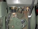
Now on to the fuel cap on the engine tank. The cap is vented but only with a one way check valve to let air in not air out. Why? What happens over time if the belly tank is used extensively? As the pump fills the engine tank air pressure will build up preventing fuel from entering. Also, injector leak off lines have combustion gasses in them and air and this will add to the tank. i do not understand why the cap is made this way. See pics. The underside rubber is very thin in the center and forms a flapper kind of seal on the center white plastic button. Air can go in but not out.
In order for the belly tank pump to deliver fuel to the tank the tank must be very low, about 1-1/2 inches of fuel. the upper float does not appear to be used and fuel level is maintaind at 1-1/2 inches, never higher. At this level the in tank fuel filter is mostly in air. Which means the filter will never be fully utilized.
Another "problem" is that the fuel exits the tank on the very bottom and only the small ridge in the filter makes a dam to stop water (which settles to the bottom) from reaching the injection pump. I believe this is a "gas" tank not a "diesel" tank. It would be much better if the tank had a small low point and a drain there. There is a drain but no separate low point for the water to collect.
All three of my units had issues with the glass sediment bowl, another hold over from the former gasoline application. I by passed them.
What I would like would be to retain the aux fuel feature, use regulated DC to run the float and pump, and be able to back feed the slave for charging a remote or on board battery. I might even think about an on board 12VDC battery and a change in fuel pump and float switch. A fuel tank cap with a manual vent open / close would be nice.
It would be nice to ditch the engine mounted tank but it is a nice feature to be able to run only on gravity feed if all the engine mounted electrics failed.
Anyway, thought some might be interested in this info.


I recently have got three of these sets up and running and all were similar in nature.
There are three electrical systems on this unit that are totally separate from each other.
The generator controls are completely inside the box and have no connection with any engine mounted or frame mounted wiring.
The starting circuit is via the slave connection and only goes to the starter. The engine's alternator circuit does not back feed the slave plug to recharge whatever battery is connected to start it. May as well unplug the slave as soon as it is running.
The engines start quite well on 12VDC at the slave as long as the decomp lever is used. The starter solenoid pulls in fine and the starter motor gets good speed if the decomp lever is used.
The engine alternator coil windings put out 50+ volts to the rectifier which is not a regulator. So 50+ volts DC is sent to the fuel tank float switch.
The float switch is rated for 24VDC and the switch is actually a switch / relay combination. So the 24VDC relay coil sees unregulated 50+ VDC. I do not like this.
If the float switch decides it is time to activate the pump then the 50+VDC is passed to an unknown component in series. The component is a mystery to me. I have pics below. It is two wire, not labeled as to wire + or - and it has an adjusting screw on it and what appears to be a flat metal base (heat sink?) I put an ohm meter across it and it behaves like a capacitor in that the meter current charges it and the meter reading changes then when the leads are reversed the reading is negative and double and the meter reading changes back. (As though the meter current used in the ohm mode is charging and discharging the device. It says Texas instruments Klixon on it. I wonder if they are just trying to provide enough resistance or regulation to match the alternator coil to the fuel pump since rpm is constant and the pump is the only device on the alternator.
Anyway from this device the signal goes to some sort of device which is either a round tube or a square box and is attached to the shielded fuel pump wire.
Voltage measured at the fuel pump during operation is around 30 VDC.
In summary, I don't like raw 50+VDC going to the relay coil or across relay contacts rated for 24VDC. I wish the engine alternator could back feed the slave to charge a battery.
Now on to the fuel cap on the engine tank. The cap is vented but only with a one way check valve to let air in not air out. Why? What happens over time if the belly tank is used extensively? As the pump fills the engine tank air pressure will build up preventing fuel from entering. Also, injector leak off lines have combustion gasses in them and air and this will add to the tank. i do not understand why the cap is made this way. See pics. The underside rubber is very thin in the center and forms a flapper kind of seal on the center white plastic button. Air can go in but not out.
In order for the belly tank pump to deliver fuel to the tank the tank must be very low, about 1-1/2 inches of fuel. the upper float does not appear to be used and fuel level is maintaind at 1-1/2 inches, never higher. At this level the in tank fuel filter is mostly in air. Which means the filter will never be fully utilized.
Another "problem" is that the fuel exits the tank on the very bottom and only the small ridge in the filter makes a dam to stop water (which settles to the bottom) from reaching the injection pump. I believe this is a "gas" tank not a "diesel" tank. It would be much better if the tank had a small low point and a drain there. There is a drain but no separate low point for the water to collect.
All three of my units had issues with the glass sediment bowl, another hold over from the former gasoline application. I by passed them.
What I would like would be to retain the aux fuel feature, use regulated DC to run the float and pump, and be able to back feed the slave for charging a remote or on board battery. I might even think about an on board 12VDC battery and a change in fuel pump and float switch. A fuel tank cap with a manual vent open / close would be nice.
It would be nice to ditch the engine mounted tank but it is a nice feature to be able to run only on gravity feed if all the engine mounted electrics failed.
Anyway, thought some might be interested in this info.