• Steel Soldiers now has a few new forums, read more about it at: New Munitions Forums!

  • Microsoft MSN, Live, Hotmail, Outlook email users may not be receiving emails. We are working to resolve this issue. Please add support@steelsoldiers.com to your trusted contacts.

My first MEP-701A / couple questions

chadande

New member
163
1
0
Location
Eau Claire, WI
Well, I picked up my first surplus generator and luckily it appears I did OK.

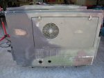
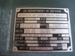
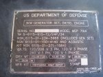
It is a 1988 MEP-016B that I assume had the ASK installed when new based on the “88” in the 701a serial number. It has a 2010 battery with a good charge and fresh clean oil in the crankcase. 591 hours on the meter.

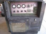
I splashed some fresh diesel in the tank to get the float lifted and it fired right up. I ran a small load of 1000w for 15 minutes and saw no significant voltage or frequency variance. I was using both the gauges on the unit and my kill-a-watt meter. Everything appears OK with the exception of battery charging.

Yes, I have read many posts and gone over both of the downloadable TM’s. These two resources have answered the majority of my questions and I feel comfortable with basic operation and maintenance, but I still have a couple questions for those of you who know more about how these sets work:

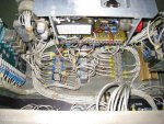
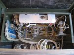
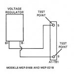
#1 Testing at the battery posts / slave receptacle shows 25.7v both running and not running which indicates the charging circuit is not working properly or at all. The TM shows to check voltage from the regulator at two test points on connector block A1-TB1 which is on the right side of the box (and has no #9), however the four wires from the regulator are connected to 3, 4, 5 & 9 on the block on the left side of the box. I see where the voltage regulator is, and where the wires go, but need help with which two to test.

#2 Inside the front panel only fuse F2 is connected to the convenience outlet, F1 appears to have never been soldered. Is that typical?
Thanks for any info in advance! :beer:
 

Attachments

Last edited:

ETN550

New member
457
9
0
Location
Knoxville, TN
Good job on your purchase. Sounds like a nice find.

Using only one fuse on the outlet is the way I have seen 100% or so of the 6 or 8 I have had through in the last year.

Open the top lid and the diagrams will indicate which numbers on your terminal are a/c and which are d/c. Or just put a meter on them with the unit off and the run switch on and you will find the + and the - . The other two are a/c from the engine flywheel and it makes no difference which is which.

The 24vdc regulator is in the back lower left, as you probably found it.

Once you know which 2 treminals are the a/c put a meter on them running. Not sure what they should be at but at least 30+ and maybe 50 vac. The yanmars make around 45vac.

If you are getting a/c then the reg is bad. Not uncommon on the 701A as many were run without batteries off of slaves or the slave was pulled off while running without a battery or with a bad battery. Keeping the battery up is more of a headache since it is behind the cover so they get neglected.

I recently replaced a regulator and found an 017a style unit for $25 but it was such a pain to adapt that if i had to do it again I would just cough up the $150 for the correct part.

Meanwhile, you could run it without the charging circuit working if you have a 24vdc charger laying around to keep the battery up.

You might surf some of my threads to see my conversions to two 12 vdc batteries. If you had (2) 12vdc batteries you could parallel the engines a/c output to (2) separate 12vdc rectifier regulators ($35.00 each) for a less expensive solution.

All in all a very good find, congrats and welcome. Lots of good people with info here!
 

Isaac-1

Well-known member
1,970
48
48
Location
SW, Louisiana
If it does turn out to be the battery charging regulator that is bad, there are new (built about 10 years ago) drop in replacements for sale on ebay for $100. Forum rules do not allow me to post a link to an ebay auction or buy it now, but you can find it by doing an ebay search for "libby regulator" It may look cosmetically different than your old one, but NSN part number matches the -24P TM and wires have the same numbers and screw holes line up. I had to change mine a few months ago when it was overcharging and cooked my battery.


Ike
 

chadande

New member
163
1
0
Location
Eau Claire, WI
Thanks ETN550 for the troubleshooting assistance. I should be able to test tonight or tomorrow and know for sure if it is bad or not.
I have a 24v tender that I could probably just permanently attach to the unit and unplug from the wall and plug into the convienience outlet when I need to run it.

Isaac-1 I saw those units on ebay, but thought it looked too different to mess with. If I need one and decided to use one of those how do you know which wire is which on the new one?
 

Isaac-1

Well-known member
1,970
48
48
Location
SW, Louisiana
each wire has a long alpha-numeric combination printed on them, these match the numbers on the old wires and on the wiring diagram (I think ones is something like F85, and other is 804A), the military spares no expense with things like custom printed wires, anyone else would put little A,B,C,D labels on the wires.
 

chadande

New member
163
1
0
Location
Eau Claire, WI
It looks like the TM was partially correct in that battery voltage is on screws 5 & 9, just on a different connector block. I'll fire it up tomorrow and see if AC is present on the other two screws.

I guess I'd rather have it be working correctly if it's between a properly set up $100 DC regulator and a cobbed together $75 battery tender.

I'll test and let you know what I find.

Thanks again for the assistance!
 

Isaac-1

Well-known member
1,970
48
48
Location
SW, Louisiana
I think it is unique to the MEP-016b and its 400Hz and maybe its 28VDC only cousins.

I know it is different from the MEP-002a and MEP-003a, not sure about the MEP-017a or MEP-018a, of course any parts for those two would likely be getting fairly old by now.

Ike

p.s. one word of warning if you do buy the ebay "libby" regulator, that may save you some headache when it comes time to install, be aware the screw holes on it are threaded, the ones on the old groove top style one are not. The both bolt into nuts on the back of the control box though, and as I said before the holes do line up.
 
Last edited:

chadande

New member
163
1
0
Location
Eau Claire, WI
I was able to fire it up and test this afternoon. I have 25.7v DC on screws 5 & 9 and 13v AC on screws 3 & 4 while running.
Any ideas? Maybe somebody could open theirs up and see what they have on a regulator that works.
 

ETN550

New member
457
9
0
Location
Knoxville, TN
Disconnect the regulator's a/c from the terminal block and see what the engine is delivering to the terminal block screws. A short in the regulator could be sucking the a/c input down when, in fact the a/c supply from the engine is okay. It's pretty hard to damage the magnet or the a/c coils on the engine. They are well protected behind the flywheel. I believe they can run sustained with direct short. Still think the regulator is the culprit.

I did fit a NOS 017A regulator I got on e-bay for $24 to this same 701A unit. BUT it was a hassle and I would not do it again. I had to make a bracket and hang it off ot the main output voltage regulator and then re-wire. Saved money though. Time was 4 hours easy. It hangs in the open on the 017A so must be tough enough.
 

chadande

New member
163
1
0
Location
Eau Claire, WI
I removed the wires to the regulator and tested on screws 3 & 4 again, but am still getting 13v AC.

I'd really hate to buy a new regulator and mess with putting it in if that isn't the problem.

Can somebody look to see if their regulator is getting AC from screws 3 & 4 and what the AC voltage is?
 

Attachments

Isaac-1

Well-known member
1,970
48
48
Location
SW, Louisiana
I will look around tomorrow and see if I still have my old one, if you want it for testing purpose your welcome to it. Note mine would slowly ramp up to full voltage after a minute or two of running and cook the batteries. I think I threw it away, but not 100% sure. Will also check screw 3 and 4 on mine, assuming we don't have more rain.

Ike
 

Isaac-1

Well-known member
1,970
48
48
Location
SW, Louisiana
I just checked mine today, and am getting 44 VAC from terminals 3 to 4 with the regulator connected, no luck on finding my old charging regulator.

Ike
 

Isaac-1

Well-known member
1,970
48
48
Location
SW, Louisiana
Best guess is damage to the windings, the bad news is they are inside the engine, so your best alternative may be a 24V battery charger/maintainer connected to the AC output.

Ike.
 

Speddmon

Blind squirrel rehabiltator
Super Moderator
Steel Soldiers Supporter
4,640
28
38
Location
Cambridge, Ohio
A number of things could be the cause.

One of them being a build-up of paint over the magnets mounted in the area surrounding the stator.

Dirt and rust covering the magnets

Missing magnets

Shorted coil or winding on the stator (probably the most likely reason)

The TM should have a test procedure for the stator with resistance values to make sure it is within tolerance.

Start by checking the resistance of the 2 A/C leads to ground. There should be none. If there is, you have a problem. Then check the resistance of the coil by checking resistance between the leads themselves. I don't know what it should be, but it will be pretty low resistance.
 

chadande

New member
163
1
0
Location
Eau Claire, WI
Each individual lead to ground is infinite resistance with the switch on off and run. Resistance between leads 3 & 4 is very low, a couple of ohms.

I'll look over the TM's again on this subject and see what I turn up.

Thanks again guys for the help on this.
 

MidKnightBomber

New member
42
0
0
Location
Salt Lake City, Utah
Just curious if the culprit to this problem was ever discovered? I recently got my first 701a and I am not sure my charging circuit is working. The only test I have performed so far was to test the voltage at the battery and the voltage did not increase much above 25.7.

What was the culprit?
 
Last edited:

chadande

New member
163
1
0
Location
Eau Claire, WI
I never got around to taking it apart enough to check the stator and magnets. Maybe this summer.
For now I just keep a battery tender on the battery to keep it fresh and charged after running the genny.
 
Top
AdBlock Detected

We get it, advertisements are annoying!

Sure, ad-blocking software does a great job at blocking ads, but it also blocks useful features of our website like our supporting vendors. Their ads help keep Steel Soldiers going. Please consider disabling your ad blockers for the site. Thanks!

I've Disabled AdBlock
No Thanks