• Steel Soldiers now has a few new forums, read more about it at: New Munitions Forums!

  • Microsoft MSN, Live, Hotmail, Outlook email users may not be receiving emails. We are working to resolve this issue. Please add support@steelsoldiers.com to your trusted contacts.


My new 1992 M998 Avenger

springer1981

Well-known member
844
1,148
93
Location
Maine
Now that the bolt is out I lined up the winch to check for clearance. One of the solenoids hit the frame before it was all the way up in place. I removed the nut and rotated the solenoid and it fit perfectly.

12.jpg


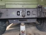
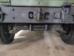
Rear winch fits like a glove.

13.jpg


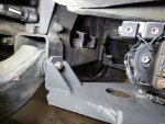
With the winch bracket in place it allows me to see what kind of space I have between the winch and the suspension. I plan to use this space to mount a rear steering hydraulic cylinder.

14.jpg
 

springer1981

Well-known member
844
1,148
93
Location
Maine
Finished mounting the winch to the control arm bolts and drilled the holes and mounted to the bumper brackets.

18.jpg


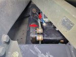
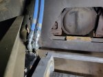
Then I had to fit the hydraulic lines to the winch motor. I had to tweak one of them to clear one of the solenoids. You can see in the picture below how the line bends slightly to the left now.

15.jpg


Then I ran the hydraulic lines to the front using the 45 degree ends in the rear. This will leave me with straight ends in the front and I wasn't sure how I was going to connect them but I'll cover that in the next post.

16.jpg
 
  • Like
Reactions: OBX

springer1981

Well-known member
844
1,148
93
Location
Maine
What's the difference between a pregnant woman and a Humvee hydraulic fitting? You can unscrew a Humvee hydraulic fitting.

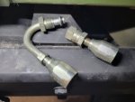
I thought they were crimped on fittings but luckily they are not. The 120 degree fitting goes to the brake booster. I had a spare hose so I removed the fittings. I'm going to replace one of the straight fittings on the line from the rear winch. Then I can connect it to the booster. I will replace the fitting that currently goes to the booster with a straight fitting which I can then connect to the other rear line.

17.jpg
 

TNDRIVER

Well-known member
Steel Soldiers Supporter
279
392
63
Location
Cleveland,TN
What's the difference between a pregnant woman and a Humvee hydraulic fitting? You can unscrew a Humvee hydraulic fitting.

I thought they were crimped on fittings but luckily they are not. The 120 degree fitting goes to the brake booster. I had a spare hose so I removed the fittings. I'm going to replace one of the straight fittings on the line from the rear winch. Then I can connect it to the booster. I will replace the fitting that currently goes to the booster with a straight fitting which I can then connect to the other rear line.

View attachment 856662
These fittings are available on line or any good hydraulic shop, its possible to make your lines up from scratch. My local guys also have the heat shield in stock. CLEANLINESS is a MUST, nothing left inside the lines when they are cut! I,ve had good luck and bad luck when replacing the ends without cutting a small amount of line off to start fresh. If you don't make a living with grease under your fingernails this is great work! My 2 cents.-
 

springer1981

Well-known member
844
1,148
93
Location
Maine
These fittings are available on line or any good hydraulic shop....
I've made lines before and I think with the extra lines I have now I should have enough fittings to do what I need to. When I get to the rear steering that might change.

....If you don't make a living with grease under your fingernails this is great work! My 2 cents.-
Thanks I do not make a living at this, just a hobby. That said, I have a few tools and toys and lots of experience with automotive, machining and mechanical work and I'm not afraid to do anything.
 

springer1981

Well-known member
844
1,148
93
Location
Maine
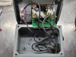
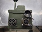
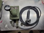
I worked on the winch control and wiring today. In a previous post I mentioned I wanted to use a Heavy Duty Winch Controller from a larger truck that most likely had a variable speed winch. The variable speed part would not apply to my winch as they just don't support it. I did find a connector to fit the winch controller. I'll make an adapter cable to plug this into the HMMWV winch connector on the dash. I wired the On/Off so the controller can't be activated by accident. I also installed a HMMWV hand winch control plug on the controller as well. This allows the Remote Winch hand control to still be plugged in and used as normal.


Here is the rewired controller.

control.jpg


Here is the newly added Remote winch hand controller plug. I will eventually paint the crew heads when I repaint the box at a later time.

control2.jpg


Here's the completed setup.

control3.jpg


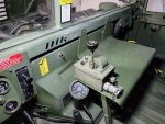
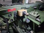
Lastly here is the future mounting location.

control4.jpg
 
Last edited:

Mullaney

Well-known member
Steel Soldiers Supporter
Supporting Vendor
7,368
19,073
113
Location
Charlotte NC
I worked on the winch control and wiring today. In a previous post I mentioned I wanted to use a Heavy Duty Winch Controller from a larger truck that most likely had a variable speed winch. The variable speed part would not apply to my winch as they just don't support it. I did find a connector to fit the winch controller. I'll make an adapter cable to plug this into the HMMWV winch connector on the dash. I wired the On/Off so the controller can't be activated by accident. I also installed a HMMWV hand winch control plug on the controller as well. This allows the Remote Winch hand control to still be plugged in and used as normal.


Here is the rewire controller.

View attachment 856784


Here is the newly added Remote winch hand controller plug. I will eventually paint the crew heads when I repaint the box at a later time.

View attachment 856786


Here's the completed setup.

View attachment 856787


Lastly here is the future mounting location.

View attachment 856789
.
Nicely done!
 

springer1981

Well-known member
844
1,148
93
Location
Maine
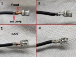
In the process of rewiring the controller I had to reuse some of the terminal pins in the connectors on the switches. I thought I would show how to do that. Some pins are harder to do this with but there are times when you have to reuse what you have.

The 5 wires circled in red needed to be redone. These are the connectors I reused.

control5.jpg


First I opened the End Crimp and wiggled the wire back and forth until it broke. I left the wire crimp with the old wire in it. Trying to uncrimp the wire crimp will likely damage the connector beyond use. After the wire was removed I used a little file on the terminal where the wire crimp is to expose the brass terminal. This will make it solder easier. Then I stripped a new piece of wire and using needle nose pliers I crimped the end on the insulation of the wire (picture 1).

Then I pulled 3 or 4 of the wire stands to each side and wrapped the around the terminal (Top Red Arrow in Picture 1). You can see them wrapped around the back in Picture 2. The wires are not twisted around each other, they are just overlapped.

In Picture 3 you can see the terminal after I soldered it. The solder adheres to the old wire that is still crimped and to the new wire. It doesn't like to adhere to the terminal itself due to oxidation on the terminal. By exposing the brass some of the solder will adhere to it.

In Picture 4 I soldered the wires in the back. This helps make sure the wire stays since it wraps around the terminal and holds it captive. I also exposed some of the brass on this side as well so it would adhere to it.

control1.jpg
 
Last edited:

springer1981

Well-known member
844
1,148
93
Location
Maine
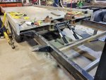
Unrelated update on this Blizzardous evening here in the Northeast. This is a side project trailer I have been working on (on and off) for a couple years as time allows. I bought this fifth wheel camper trailer frame with hitch and everything with ambitions of making a car hauler trailer out of it. Then I came across a Jerdan 19ft rollback bed and managed to practically steal it. Last year I started mating the two and in the last couple of months focused more time and effort into it, after the 4L80 swap. I rebuilt the long cylinder that slides the bed and just picked up the lift cylinders.

I reinforced the trailer even though it was rated for 14,000 lbs. Today I finished up mounting the lift cylinders. I still have to run all the hydraulics, wire the lights, wire the brakes, mount the winch and more but the structure is done.

Here's a couple pictures. Someday it might haul the Humvee !!

Trailer1.jpg

Trailer2.jpg
 

springer1981

Well-known member
844
1,148
93
Location
Maine
Today I started working on the rear steering. As some of you might have seen there is someone making a rear steering cylinder with auto mechanical centering. I looked at that system closely before deciding I don't like the way it works. Basically it uses spring pressure and a bleed off hole to return the piston back to the center. When you apply hydraulic pressure it moves the piston right or left and as soon as you stop applying pressure it immediately starts returning to the center position again by bleeding the hydraulic fluid off to the other side. There is very little control, you either have full steer or it is returning to center. No partial steering, no way to hold it at a partial steer, it's all or nothing. I want to be able to move it 25% or 33% or 50% or 100% or anything in between and have it stay until I want it to return to center.

One of the selling points that sounds great on the surface it No Wiring to rip out while 4 wheeling. I thought about that also and our HMMWV's have plenty of protection under them and places to run wiring that it was one of the least concerning things to me. I get not having sensors and other electronics to deal with but wires and solenoids like the winch uses would not be an issue in my opinion. Also I really looked over that other cylinder and after some research I found not all steering cylinders are equally made. PSC makes probably the best, most reliable and least problematic hydraulic steering cylinders available. Ultimately that was number 1 deciding factor to not use the other system and to make my own.

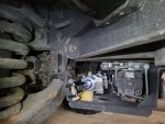
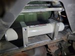
In the pictures below I was test fitting the cylinder. The first picture locates it in front of the rear winch.

RS1.jpg


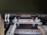
This picture is looking between the bed and the rear bumper. The mount just above the cylinder, I believe it was a tool mount?, it's where I plan to mount the hydraulic control valve. The other system mentioned above requires the additional purchase of an electric hydraulic pump. I plan to use the power steering pump to drive mine and can tap the rear hydraulic winch lines you see on the left side of the picture. So I won't have to run any additional hydraulic lines, pump, 12v system, or the "up/down" button pendant controller in the cab.
RS2.jpg


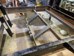
This is the bottom view looking up. The rear winch bracket is on both the left and right side of the picture and is made out of steel. I plan to make bracket that will bolt to the rear winch bracket to mount the cylinder mounts too.
RS3.jpg


Part of the plan is to use a turret joystick control to control the rear steering. Conveniently the joystick only moves left and right and is labeled Left and Right on the control. I plan to add an On/Off switch that locks in the off position like the one on the winch controller. This will prevent accidental rear steer operation.

I haven't decided exactly how I want the control to center. I was thinking about adding a centering button to auto return to center and maybe adding a LED light to indicate when it isn't centered. LED would turn off when it's centered. The other system mentioned above uses a bleed off hole in the piston that allows the hydraulic fluid to equalize when centering however that also means that force place on the tire can cause it turn by allowing fluid to pass from side to side in that cylinder. I won't have a bleed off hole so my rear steering cylinder will be hydraulically locked preventing any "bump" or corning steer from happening when centered for normal road driving.
RS4.jpg
 

TOBASH

Father, Surgeon, Cantankerous Grouch
Steel Soldiers Supporter
3,269
3,009
113
Location
Brooklyn, NY
I have enough trouble keeping the front wheels straight and on the pavement. Adding two more wheels to the equation will be sure to make sidewalks and the first and second stories in many buildings unsafe.
 

springer1981

Well-known member
844
1,148
93
Location
Maine
I dug into the controller I bought on epay for $35 from Beltfed. It was advertised as "inop" and I had planned on needing to fix or modify it for my application so it was the right price for me. In working condition they seem to go for a lot. If you are in need of one of these I would recommend risking buying one that is inop and fixing it.

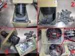
To take it apart I removed the obvious screws but it would not simply come apart. I then used a big fine tuning tool (dead blow hammer) and beat it solidly on the sides until it separated a little and I could get a screwdriver in to pry it apart. What I found (Picture 1) was a rubber sealed unit. When it was assembled a liquid rubber compound was poured in and hardened after assembly. The wires were very short and cast into the rubber. If this was going to be repaired I would start at the where the wire goes into the rubber and carefully dig a little out for some extra slack in the wire. More on the repair later.

After it was apart I dug all the rubber out (picture 2 and 3) using needle nose pliers and being careful around the wires.

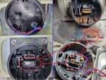
After all the rubber was out I removed the cover from the back of the joystick and found the small circuit board dislodged from its mounting. It was just dangling inside the cover (picture 4, bottom circle). I pressed the board back into its holder (picture 4, top circle) and placed the little wire holder back as well (picture 4, Red Square). It would have been fixed at this point and it could have been reassembled and used. If the intention was to fix this, none or very little rubber would have had to be removed and in the end it was a simple fix.

control1.jpg

I considered trying to use the existing electronics for my application but ultimately decided against it and here is why.

I have never used or even seen a turret or turret control in person but I will make some assumption and hopefully someone that has can tell me if I am right or not. The little circuit boards primary component is a Hall Effect Sensor (magnetic sensor). I did a quick search but couldn't find specific information about this exact sensor but I did find what I believe is basically the same thing and found the datasheet for it. This little 4 pin sensor (picture 4, bottom circle above) is a Programmable Linear Hall Effect sensor so I believe the turret movement is based on how much you push the joystick left or right. It is not simply an On/Off stick that moves it left or right but also varies the speed at which it moves the turret. Push it a little and it moves slow, push it all the way and it moves faster.

For me, it simply needs to activate a solenoid valve for left or right turning. It would be possible to utilize the setup "as is" and control a servo motor attached to a hydraulic orbital valve and build a proportional rear steering system but that is a lot more work than I want to undertake. Instead I have gutted the joystick and I will rebuild it using micro switches to simplify its operation for my needs. I will post more as I do it.

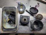
Here is what it looks like now.
control2.jpg
 
  • Like
Reactions: OBX

TOBASH

Father, Surgeon, Cantankerous Grouch
Steel Soldiers Supporter
3,269
3,009
113
Location
Brooklyn, NY
I dug into the controller I bought on epay for $35 from Beltfed. It was advertised as "inop" and I had planned on needing to fix or modify it for my application so it was the right price for me. In working condition they seem to go for a lot. If you are in need of one of these I would recommend risking buying one that is inop and fixing it.

To take it apart I removed the obvious screws but it would not simply come apart. I then used a big fine tuning tool (dead blow hammer) and beat it solidly on the sides until it separated a little and I could get a screwdriver in to pry it apart. What I found (Picture 1) was a rubber sealed unit. When it was assembled a liquid rubber compound was poured in and hardened after assembly. The wires were very short and cast into the rubber. If this was going to be repaired I would start at the where the wire goes into the rubber and carefully dig a little out for some extra slack in the wire. More on the repair later.

After it was apart I dug all the rubber out (picture 2 and 3) using needle nose pliers and being careful around the wires.

After all the rubber was out I removed the cover from the back of the joystick and found the small circuit board dislodged from its mounting. It was just dangling inside the cover (picture 4, bottom circle). I pressed the board back into its holder (picture 4, top circle) and placed the little wire holder back as well (picture 4, Red Square). It would have been fixed at this point and it could have been reassembled and used. If the intention was to fix this, none or very little rubber would have had to be removed and in the end it was a simple fix.

View attachment 858145

I considered trying to use the existing electronics for my application but ultimately decided against it and here is why.

I have never used or even seen a turret or turret control in person but I will make some assumption and hopefully someone that has can tell me if I am right or not. The little circuit boards primary component is a Hall Effect Sensor (magnetic sensor). I did a quick search but couldn't find specific information about this exact sensor but I did find what I believe is basically the same thing and found the datasheet for it. This little 4 pin sensor (picture 4, bottom circle above) is a Programmable Linear Hall Effect sensor so I believe the turret movement is based on how much you push the joystick left or right. It is not simply an On/Off stick that moves it left or right but also varies the speed at which it moves the turret. Push it a little and it moves slow, push it all the way and it moves faster.

For me, it simply needs to activate a solenoid valve for left or right turning. It would be possible to utilize the setup "as is" and control a servo motor attached to a hydraulic orbital valve and build a proportional rear steering system but that is a lot more work than I want to undertake. Instead I have gutted the joystick and I will rebuild it using micro switches to simplify its operation for my needs. I will post more as I do it.

Here is what it looks like now.
View attachment 858153
Somewhere there is now a turret that will never spin again. 😢

Great work. You will have a truly unique fun truck.
 

springer1981

Well-known member
844
1,148
93
Location
Maine
Turns out not all failures are created equal. After taking the turret joystick apart and finding the loose sensor and "fixing it", I decided to buy another joystick. The rubber boot on the first is a little deformed from use or heat or something. I bought the second joystick in hopes of getting a better boot and maybe fixing it also. Turns out they don't seem to be as sealed as they could be. This one clearly had moisture in it and the magnet rusted away.

On the left side is the first one I bought and in the bottom half you can see the magnet all nice and shiny. On the right side is the second one and the magnet was not only rusted but all swelled up and beyond repair. The magnet is circled in Red showing how bad it was. The bottom picture is what it looked like right after I opened it up.

Magnet.jpg
 

springer1981

Well-known member
844
1,148
93
Location
Maine
I considered trying to use the existing electronics for my application but ultimately decided against it and here is why....

....For me, it simply needs to activate a solenoid valve for left or right turning. It would be possible to utilize the setup "as is" and control a servo motor attached to a hydraulic orbital valve and build a proportional rear steering system but that is a lot more work than I want to undertake. Instead I have gutted the joystick and I will rebuild it using micro switches to simplify its operation for my needs. I will post more as I do it.
In the above quote I explained the "plan" for simplicity and not taking the more difficult and costly route of building a proportional rear steering. That said, I don't really have a plan I just kind of dive in and see where things take me. The more I thought about what I wrote about not doing, the more I wanted it. Since I was able to "fix" the joystick (untested) I considered getting the appropriate control if I could find one at a reasonable price, I did. Then I started looking for a turret motor. I opted for an "inop" that was pretty inexpensive figuring I could fix it myself, how bad could it be? It's only a motor and gear box.

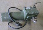
Here's the one I bought ... Looks lightly used at best. Has a few bumps and dings and a broken connector. Looks like a good place to start.

motor1.jpg


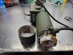
I pulled the rear cover off the motor to start and was immediately greeted with lots of oxidation and corrosion. The corroded piece on the rear of the motor is a brake.

motor2.jpg


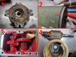
I removed the brake (number 1 below) and proceeded to take it apart. only 1 of the 3 screws would come out and I had to drill the other 2. Once I got it apart I figured out it was a brake or more so a holding brake to prevent the motor from turning when stopped.

In picture number 2 I noticed it was missing the o-ring seal. I believe this was not installed during manufacturing. I believe I am the first person to take it apart. I also believe this is a the root of all the problems with this motor.

Picture 3 is the gearbox. I am not sure what the lubrication is. It's something between AFT and axle grease in consistency. I noticed some coagulation type stuff in the grease. It just doesn't seem right and I removed it all. The piece of wood was used to disengage the gear so I could remove the motor.

Picture 4 is the disassembled motor. The magnets were dislodged from the case and one is broken. The bearings were frozen and the brushes frozen. The armature is good and I was able to save the brushes that were barely worn.

motor3.jpg


Now the challenge begins. The bearings should be easy to replace and the armature will clean up nice but finding new magnets might be hard. I think I could replace the motor but I would either have to find an exact replacement or find a 2 pole motor of the same size and use the magnet section to rebuild this motor. The gear on the end of the armature is part of the armature and part of the gearbox function.
 

springer1981

Well-known member
844
1,148
93
Location
Maine
I learned a lot about the Turret motor assembly. First it's made in China!! Or at least the motor is but I suspect it is entirely made in China. That explains the missing o-ring in manufacturing and ultimately the total failure. That said it's nothing more than a Mobility wheelchair drive system and there are tons of them on epay that are basically the same thing but many variations. There is a right and a left drive for the chair and the turret uses the left drive (depending on manufacturer). Also the motors on the chairs can be 22.5 or 24vdc of course the turret is 24vdc. There are different drive ratios as well, the turret is a 29:1. This is important because there are 2 typical motors, a 4 pole and a 2 pole. A 4 pole (4 brushes in the motor) turns at 1800 RPM max and the 2 pole (2 brushes) turns at 3600 RPM max. A 4 pole motor has half the speed and twice the torque. With a 4 pole motor half the drive ratio would be required to obtain the same final speed, roughly 14:1.

There are several versions of turret drives and they are not all alike. I'm using the one I have as an example and this may not apply to other version but I suspect there are some similarities.

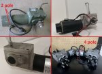
The picture below shows my turret drive and notes the 2 brushes (2 pole motor), 3600 RPM. The wheelchair drive beside and below it is also a 2 pole design. The gear system is is almost the same with minor exceptions. The shaft would even take the sprocket from the turret drive. And the disengage handle could be swapped and fit right on. They are basically the same. A little water proofing and some green paint and they would look the same. The bottom right picture shows a different type with both right and left wheelchair drive motors, wheel hubs and 4 pole motors for example purposes. They are 12:1 ratio 4 pole and would be equivalent to 24:1 2 pole system.

m1.jpg
 

TNDRIVER

Well-known member
Steel Soldiers Supporter
279
392
63
Location
Cleveland,TN
I learned a lot about the Turret motor assembly. First it's made in China!! Or at least the motor is but I suspect it is entirely made in China. That explains the missing o-ring in manufacturing and ultimately the total failure. That said it's nothing more than a Mobility wheelchair drive system and there are tons of them on epay that are basically the same thing but many variations. There is a right and a left drive for the chair and the turret uses the left drive (depending on manufacturer). Also the motors on the chairs can be 22.5 or 24vdc of course the turret is 24vdc. There are different drive ratios as well, the turret is a 29:1. This is important because there are 2 typical motors, a 4 pole and a 2 pole. A 4 pole (4 brushes in the motor) turns at 1800 RPM max and the 2 pole (2 brushes) turns at 3600 RPM max. A 4 pole motor has half the speed and twice the torque. With a 4 pole motor half the drive ratio would be required to obtain the same final speed, roughly 14:1.

There are several versions of turret drives and they are not all alike. I'm using the one I have as an example and this may not apply to other version but I suspect there are some similarities.

The picture below shows my turret drive and notes the 2 brushes (2 pole motor), 3600 RPM. The wheelchair drive beside and below it is also a 2 pole design. The gear system is is almost the same with minor exceptions. The shaft would even take the sprocket from the turret drive. And the disengage handle could be swapped and fit right on. They are basically the same. A little water proofing and some green paint and they would look the same. The bottom right picture shows a different type with both right and left wheelchair drive motors, wheel hubs and 4 pole motors for example purposes. They are 12:1 ratio 4 pole and would be equivalent to 24:1 2 pole system.

View attachment 859571
I AM AMAZED I wish you were my neighbor! You are an engineer .....right?
 

springer1981

Well-known member
844
1,148
93
Location
Maine
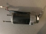
I found a 2 pole motor on epay and asked for the dimensions. The motor has the same diameter and length body so I'm hoping the magnets are the same. It's a gamble but I think it's a safe bet. I was also able to remove the bearings and seal to order new ones. Hopefully it will be like new when I'm done.

For some reason it's more satisfying buying a broken turret drive for $100, a motor for parts for $50, a handful of bearings, seals and o-rings for $40 and then spend 3 weeks working on it rather than buy a working one for $250.

Here's the parts motor

M2.jpg
 
Top
AdBlock Detected

We get it, advertisements are annoying!

Sure, ad-blocking software does a great job at blocking ads, but it also blocks useful features of our website like our supporting vendors. Their ads help keep Steel Soldiers going. Please consider disabling your ad blockers for the site. Thanks!

I've Disabled AdBlock
No Thanks