• Steel Soldiers now has a few new forums, read more about it at: New Munitions Forums!

  • Microsoft MSN, Live, Hotmail, Outlook email users may not be receiving emails. We are working to resolve this issue. Please add support@steelsoldiers.com to your trusted contacts.


My no power troubleshooting thread Mep-804a. “5”

Jeep Nasty

Active member
379
242
43
Location
NH
So on the advice of Guy fang I decided to start a separate thread for my first generator that I’m going to troubleshoot the quotation marks show number five and that’s just because this is the number that this generator was tagged with on the side of it when I got it.

Engin starts and runs

It shows no real movement on HZ. It will barely go above the 48 Hz and if I dial it all the way up I hear the engine speed increase lately but there’s no movement on the gauge.

And voltage only shows about 25volts. With no changes when I turn up the dial.

Oil pressure gauge shows Nothing. It does have 24v at I terminal and about 4.8v at s terminal when running. I think gauge may be shot.

I added the fuse mod I got from Kurt.

I tried to check resistance on the exciter circuit by measuring resistance on A-1 wires from terminals 1&3
Before I start discussing my results I just want to say that I am no way shape or form an electrical engineer and I only Know just enough to be dangerous.

I’m concerned I may have issues with some of my equipment and while I use a multimeter a lot to check for continuity and basic voltage I don’t have a lot of practice measuring resistance.

When I first took the measurements on those two wires I was getting 7.8 mega ohms and 4.5 mega ohms depending on which and I had the leads on. I always thought resistance did not matter on the direction so I’m confused. Now when I’m trying to measure the resistance I’m getting 0L and sometimes I’m getting up to 15.3 mega ohms.

Here are the initial photos before I start pulling anything else apart and checking stuff.


Sent from my iPhone using Tapatalk
 

kloppk

Well-known member
Steel Soldiers Supporter
1,976
3,071
113
Location
Pepperell, Massachusetts
Wires that are on A1-1 & A1-3 are the wires that lead to the exciter.
The resistance you should read between those two wire when removed from A1 should be ~ 28 to 39 ohms.
Getting a megaohm reading could indicate a couple of problems.
1) Bad Exciter winding
2) Problem with wiring as is goes from A1 to the exciter.

Things to check are....
1) Check the resistance between the two terminals on TB8. It should be ~ 28 to 39 ohms.
This is the junction between the wiring from A1 to the exciter leads from the gen head.
If you measure ~ 28 to 39 ohms there then there is an issue with the wiring from A1 to TB-8
The two exciter signals from A1 to TB8 pass thru the P5/J5 connection on pins 28 & 29. Might want to check that P6 & J6 are properly connected.

A1-1 lead goes to TB4-16. From there is goes to the J5-29/P5-29 connection. From P5-28 it goes to TB8-2.
A1-3 lead goes to TB4-13. From there it goes to the J5-28/P5-28 connection. From there it goes to TB8-1.
 

Guyfang

Moderator
Staff member
Moderator
15,902
22,179
113
Location
Burgkunstadt, Germany
Kurt has gotten you started. I will add a bit here also.

It shows no real movement on HZ. It will barely go above the 48 Hz and if I dial it all the way up I hear the engine speed increase lately but there’s no movement on the gauge. (The reason you have no moment is because you have no AC output. Hertz is in relation to AC output.)

And, (AC) voltage only shows about 25volts. With no changes when I turn up the dial. (That's all you can get, when the main gen is not excited, and producing power.)

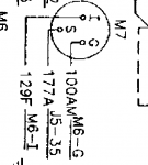
Oil pressure gauge, (M7) shows Nothing. It does have 24v at I terminal and about 4.8v at s terminal when running. I think gauge may be shot. (Do not assume anything. Test. Open TM 9-6115-643-24 to PDF reader page#141. See para: 2-25 Fuel Oil Pressure Indicator. Read the procedure 2 times through. Then do the test for the meter. ALSO, before doing it, look at:

1639345761032.png
Are your wires hooked up correctly?
 

Jeep Nasty

Active member
379
242
43
Location
NH
Wires that are on A1-1 & A1-3 are the wires that lead to the exciter.
The resistance you should read between those two wire when removed from A1 should be ~ 28 to 39 ohms.
Getting a megaohm reading could indicate a couple of problems.
1) Bad Exciter winding
2) Problem with wiring as is goes from A1 to the exciter.

Things to check are....
1) Check the resistance between the two terminals on TB8. It should be ~ 28 to 39 ohms.
This is the junction between the wiring from A1 to the exciter leads from the gen head.
If you measure ~ 28 to 39 ohms there then there is an issue with the wiring from A1 to TB-8
The two exciter signals from A1 to TB8 pass thru the P5/J5 connection on pins 28 & 29. Might want to check that P6 & J6 are properly connected.

A1-1 lead goes to TB4-16. From there is goes to the J5-29/P5-29 connection. From P5-28 it goes to TB8-2.
A1-3 lead goes to TB4-13. From there it goes to the J5-28/P5-28 connection. From there it goes to TB8-1.
I’ll try to run all those down tomorrow. I also ordered a new set of leads for my multimeter. So that I can verify my equipment is working properly before I start basing my findings off of that.


Sent from my iPhone using Tapatalk
 

Jeep Nasty

Active member
379
242
43
Location
NH
Wires that are on A1-1 & A1-3 are the wires that lead to the exciter.
The resistance you should read between those two wire when removed from A1 should be ~ 28 to 39 ohms.
Getting a megaohm reading could indicate a couple of problems.
1) Bad Exciter winding
2) Problem with wiring as is goes from A1 to the exciter.

Things to check are....
1) Check the resistance between the two terminals on TB8. It should be ~ 28 to 39 ohms.
This is the junction between the wiring from A1 to the exciter leads from the gen head.
If you measure ~ 28 to 39 ohms there then there is an issue with the wiring from A1 to TB-8
The two exciter signals from A1 to TB8 pass thru the P5/J5 connection on pins 28 & 29. Might want to check that P6 & J6 are properly connected.

A1-1 lead goes to TB4-16. From there is goes to the J5-29/P5-29 connection. From P5-28 it goes to TB8-2.
A1-3 lead goes to TB4-13. From there it goes to the J5-28/P5-28 connection. From there it goes to TB8-1.
I’m getting Mega ohm reading at the TB8

Good readings on the A1 1&3 wires all the way to TB8


Sent from my iPhone using Tapatalk
 

kloppk

Well-known member
Steel Soldiers Supporter
1,976
3,071
113
Location
Pepperell, Massachusetts
I assume the two exciter wires from the exciter were on the TB8 terminals when you di the measurement.
If so then you ought to inspect the leads to TB8 from the exciter. Hopefully you can find a break explaining the high resistance.
I've see the exciter leads on a few 802's and 803's break or get chewed thru right where the wires enter the gen head housing.
If all looks good external to the the gen head then it's time to peek inside and check the wires all the way up to the exciter itself.
 

Guyfang

Moderator
Staff member
Moderator
15,902
22,179
113
Location
Burgkunstadt, Germany
Kurt wrote:
If so then you ought to inspect the leads to TB8 from the exciter. Hopefully you can find a break explaining the high resistance. I've see the exciter leads on a few 802's and 803's break or get chewed thru right where the wires enter the gen head housing.
This is a rather common failure. Sometimes they get pinched, chafed or four legged friends chew on them. Remove wires 140D and 141D, before measuring the wires G1-F1 and G1-F2. Then from both the F1 and F2 wires to ground.


1639869810612.png
 

Jeep Nasty

Active member
379
242
43
Location
NH
Kurt wrote:
If so then you ought to inspect the leads to TB8 from the exciter. Hopefully you can find a break explaining the high resistance. I've see the exciter leads on a few 802's and 803's break or get chewed thru right where the wires enter the gen head housing.
This is a rather common failure. Sometimes they get pinched, chafed or four legged friends chew on them. Remove wires 140D and 141D, before measuring the wires G1-F1 and G1-F2. Then from both the F1 and F2 wires to ground.


View attachment 853618
Looks like I need to go. Into the gen head with wires disconnected, nothing and lead looked clean all the way into head housing.
I’ve never opened a gen head so I guess I have some reading to do.


Sent from my iPhone using Tapatalk
 

Guyfang

Moderator
Staff member
Moderator
15,902
22,179
113
Location
Burgkunstadt, Germany
Please do read the TM's. But its not hard. Remove the rear lower panel, TM-9-6115-643-24P, Figure #4, Item # 22. Should be 31 screws. At that point, you should be able to pull the two wires down into plain sight, and give them a look see. Follow them up to the place they go into the main gen. If by then you have not found a break/problem, then you need to do a bit more work. Remove the End Bell cover, Figure #25, Item # 16. Take the 4 ea. bolts out. Then if I remember right, there are two threaded holes to screw in some bolts to force the cover off the bearing. The Roter will drop a tad, so I ALWAYS took the battery cables off. Should someone inadvertently turn on the S1, you can go directly to the shower room. Follow the wires up to the exciter coils, (we called them Bobbens). I hope you find the problem before you get that far. If the Bobbens are damaged? Well, we just replaced the Exciter Stator and went home for lunch. You might be able to find a take off someplace. Hope for a broken/cut wire someplace. Do not think this is some sort of rocket science. Its not, and I think it is easy to check. BUT DO READ UP FIRST.
 
Top
AdBlock Detected

We get it, advertisements are annoying!

Sure, ad-blocking software does a great job at blocking ads, but it also blocks useful features of our website like our supporting vendors. Their ads help keep Steel Soldiers going. Please consider disabling your ad blockers for the site. Thanks!

I've Disabled AdBlock
No Thanks