

cucvegas
Member
- 59
- 14
- 8
- Location
- NW Arkansas
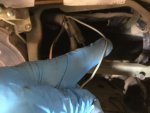
Could someone tell me where this gray wire is supposed to be connected (pictured with blue glove holding it)? It looks like it goes to the heater switch or volt meter?
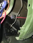
The second picture shows the red power wire it was spliced in to (I think???) by the previous owner. Any ideas what it was powering?
Does it have to do with the voltage drop resistors when selecting the blower speed?
The reason I’m asking is the previous owner also ran a manual switch that would send power directly to the blower motor. This switch did not work when I got it, so I disconnected it and re-connected the original wire from the resistors to the blower motor just to try it.
strangely enough, the blower now works with the original blower switch on high but not mid 1 or mid 2. I don’t know why the previous owner ran the wire on a manual switch in the first place.
Could someone also kindly direct me to the page number and which TM shows the wiring diagram and how to trouble shoot with a volt meter if it is the switch or resistors? I couldn’t find it in -20 TM.
Thanks!
Attachments
-
 2.4 MB Views: 48
 -
 968 KB Views: 46

