2Pbfeet
Well-known member
- 241
- 417
- 63
- Location
- Mt. Hamilton, CA
Upfront, I just want to say how invaluable this forum is. I have been reading for a few years, and it gave me the confidence that I might be able to get an MEP-803A up and running.
Not there yet. But I bought one.
Backstory: I just picked up an '06 MEP-803A, with 22 hours on it. Given the age, and the low hours, I figure that something happened early in its life, and folks didn't have time to trouble shoot it, and it got parked out back.
Apparently it was originally a genset on a M151A2 for the 127th. At some point it parted company with the trailer.
I'm working my way through cleaning it up ( mouse nests, wasp nests), swapping in the well nut tank fix (it leaks diesel), changing all the fluids plus filters, and putting in @kloppk's upgraded voltage regulator.
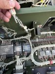
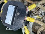
I noticed that the wire between the ground lug on the power panel and the engine frame is charred, (100E?). As in down to bare wire in some places, insulation missing in a number of places, and black and toasted along its length.
Where do I find what the correct wire gauge for 100E is? Any tips on sources? I'm sure it is obvious, somewhere, but I am still learning how the TMs function, and I can't seem to match that wire to a gauge or part number. I'm assuming that they are all made up from stock as needed. Needless to say, I can't read the markings on the actual wire.
Any thoughts on how someone might have toasted the ground wire from the engine frame to ground lug, and what else might be a casualty, or at least worth looking at?
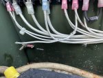
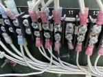
Some rodent also had fun chewing on what I think is the EMI shields between the power lugs. Is there a source for them, or a circuit? I think that it is the AFCON 88-20527, for the ground to neutral connection. (I believe it is a 0.5W 1Mohm resistor and a .1uF, plus a 1.0F capacitor.)
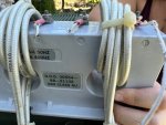
Finally, there is the remains of a nest behind the cube (S") . What is the best way into get there? Top and upper side panels off?
. What is the best way into get there? Top and upper side panels off?
Thanks!
All the best,
2Pbfeet
Not there yet. But I bought one.
Backstory: I just picked up an '06 MEP-803A, with 22 hours on it. Given the age, and the low hours, I figure that something happened early in its life, and folks didn't have time to trouble shoot it, and it got parked out back.
Apparently it was originally a genset on a M151A2 for the 127th. At some point it parted company with the trailer.
I'm working my way through cleaning it up ( mouse nests, wasp nests), swapping in the well nut tank fix (it leaks diesel), changing all the fluids plus filters, and putting in @kloppk's upgraded voltage regulator.
I noticed that the wire between the ground lug on the power panel and the engine frame is charred, (100E?). As in down to bare wire in some places, insulation missing in a number of places, and black and toasted along its length.
Where do I find what the correct wire gauge for 100E is? Any tips on sources? I'm sure it is obvious, somewhere, but I am still learning how the TMs function, and I can't seem to match that wire to a gauge or part number. I'm assuming that they are all made up from stock as needed. Needless to say, I can't read the markings on the actual wire.
Any thoughts on how someone might have toasted the ground wire from the engine frame to ground lug, and what else might be a casualty, or at least worth looking at?
Some rodent also had fun chewing on what I think is the EMI shields between the power lugs. Is there a source for them, or a circuit? I think that it is the AFCON 88-20527, for the ground to neutral connection. (I believe it is a 0.5W 1Mohm resistor and a .1uF, plus a 1.0F capacitor.)
Finally, there is the remains of a nest behind the cube (S
Thanks!
All the best,
2Pbfeet


") .
.