• Steel Soldiers now has a few new forums, read more about it at: New Munitions Forums!

  • Microsoft MSN, Live, Hotmail, Outlook email users may not be receiving emails. We are working to resolve this issue. Please add support@steelsoldiers.com to your trusted contacts.


Picked up 6 MEP-802A gensets and will be documenting making them all runners here

pclausen

Well-known member
Steel Soldiers Supporter
452
281
63
Location
Afton, VA
Got a chance to load test this set with the Stator swapped in from the spare unit. At first it was smoking a little since the new rings had not seated yet, but that cleared up after a few minutes under load. I didn't do extended load testing since I didn't have the top covers on it yet.


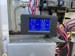
It does smoke a little during the 6,200 watt test, but I think that is to be expected. The good news is that the load meter works, and the frequency meter sort of does as well, although as I increase the rpms, I can't get it to register past 59.5 Hz, but maybe it will free up after more use. Still waiting on the main AC Voltmeter from Newark and the 3 small gauges from vehiclecontrols.com, but that should be it for instrumentation on this set, unless I can't get the frequency meter to move past 59.5 Hz.

After the load testing, I got the roof pieces straightened out the best I could and with some persuasion, was able to get them installed. Its the unit in the foreground.

IMG_0632.JPG

IMG_0633.JPG

The unit behind it is the 32 hour one with a blown head gasket and the one behind it with the white siding on top, is the spare parts one. If you look closely, there is also a unit behind the Ford tractor. That's the first one I rebuild back in 2014 with the engine painted Ford Blue. That one should be good to go except I need to replace the fuel sending unit. The last one is still up in my garage, and is the one that turns over but won't fire due to low compression. I plan to tackle that one next, but will create a new thread for it.

Anyway, back to the unit I'm wrapping up, as you can see from the first picture above, its missing the control panel cover. I did get that long section of aluminum hinge and cut off a section, drilled the holes, and got it painted:

IMG_0639.JPG

Hopefully it will bolt right up.
 
Last edited:

pclausen

Well-known member
Steel Soldiers Supporter
452
281
63
Location
Afton, VA
Pretty crappy weather here in VA today, but I did manage to get the new hinge bolted on:

IMG_0654.JPG

That fresh new paint makes the rest of the set look pretty dull, lol.

Didn't really want to start load testing the 3 running 802 sets to make a note of anything left that needs to be addressed with them, so I decided to remove the 803 from its trailer and drop it in the shop for a closer look.

IMG_0644.JPG

IMG_0645.JPG

I popped the top cover and installed the fuse/mov mods and blew out all the dust and what not. It looks pretty clean:

IMG_0650.JPG

The wires going down to the load lugs are definitely thicker than on a 802, which makes sense.

IMG_0651.JPG

I also noticed that this set uses Philips head screws for the hinge, which is the only unit I have seen with those:

IMG_0646.JPG

Also found this in the storage compartment:

IMG_0652.JPG

So it seems that this unit was decommissioned in 2020.
 

pclausen

Well-known member
Steel Soldiers Supporter
452
281
63
Location
Afton, VA
I decided to tear into the 802 that would crank but not start, not even with ether. So compression was likely too low.

Muffler and intake removed:

IMG_0658.JPG

I heard something rattle in the intake tube and found a nut in it. Also found 2 small metal pieces in the front intake of the head itself:

IMG_0659.JPG

I guess a rodent got in there while it was sitting for 7 years without the intake filter installed.

So I would say it was a very good thing that the engine did NOT fire!

Water pump and valve covers removed:

IMG_0660.JPG

And here's the underside of the head:

IMG_0661.JPG

I'll clean off the head gasket material, but otherwise it looks like just it did when I bolted it on back in 2014. The block with the head gasket still on:

IMG_0662.JPG

No reusing that gasket...

IMG_0663.JPG

I'm surprised it deteriorated that much just from sitting for 7 years. Top of block with gasket removed:

IMG_0664.JPG

Closeup of cylinder wall:

IMG_0665.JPG

I for sure never honed the bores on this one back in 2014...

Time to drain the oil and pull the pistons out I suppose.

Went ahead and ordered a couple of head gaskets, one for this set and one for the one with 32 hours on it that is leaking coolant at the head gasket. $25 shipped per gasket is quite a bit less than I paid for them back in 2014 I'm pretty sure.
 
Last edited:

pclausen

Well-known member
Steel Soldiers Supporter
452
281
63
Location
Afton, VA
Got the side cover off:

IMG_0669.JPG

Gasket stayed with the cover and is in one piece still:

IMG_0675.JPG

It is separating in a couple of places. I'll see if I can carefully remove it and re-use it. If not, I'm thinking I'll just use some make a gasket silicone sealer.

It is very nasty inside the crankcase:

IMG_0674.JPG

IMG_0679.JPG

There's a film of oil all along the inside wall at the level where the oil was. I'll spend some quality time tomorrow trying to get all that cleaned out before I remove the caps to pull the pistons out.

Got the head gasket material removed from the block:

IMG_0680.JPG

And the head:

IMG_0682.JPG

Sprayed it down with some WD40 to keep surface rust at bay.
 

pclausen

Well-known member
Steel Soldiers Supporter
452
281
63
Location
Afton, VA
Got the crankcase cleaned out:

IMG_0684.JPG

I pulled the pistons. The top ring was seized in both pistons. Here's #1 after prying it out:

IMG_0685.JPG

And #2 still on the piston, but freed up:

IMG_0687.JPG

The middle ring was partly stuck on both pistons and the lower ring was free on both.

I'm going to clean out the grooves and then use new rings during re-assembly.

Once I get it all back together, I think the odds of it starting this time, are much improved. :)
 

DieselAddict

Well-known member
Steel Soldiers Supporter
2,482
1,881
113
Location
Efland, NC
I have found over the years of building engines that once you get the engine running and you know its OK, get a load on it. Its especially important for the top ring to have plenty of pressure on it to get it to seat in the bore. You have a limited amount of time after a hone to get this done. For the first heat cycle run it at about 25 - 40% load for at least an hour then shut it down and let it FULLY COOL DOWN. Second time start it, get some heat in it then run it at 25% and ramp up to at least 75% load and hold it for at least an hour. Let it cool down fully then start it and ramp the load up to MAX. I won't hold it at MAX but a few minutes then bring it down to maybe 90% for a half hour. During that time I'll check the crankcase for pressure and exhaust temperature balance. By this time the rings should be seated well enough you shouldn't see any pressure. The engine should be ready for service at this point. Its not fully broken in but the rings should be good to go and the rest will wear in over the remainder of the break in period.

After each run (depending on the engine) I do things like check valve lash and valve spring height, cam timing, crank end-play.
 

pclausen

Well-known member
Steel Soldiers Supporter
452
281
63
Location
Afton, VA
Great advice Chris. I'll be sure to follow that break-in process on this set once I get it going. Will be sure to do that to the other 2 sets that I honed back in 2014, but have only run one maybe 30 minutes tops so far back in 2014. The 2nd one I honed back than has also only run for maybe 30 minutes total, a few weeks ago. Sitting 7 years without running was probably not the greatest for them, but hopefully that will be ok after following the above procedure.

Started honing the bores, but it is a slow process with the 240 grit stones I have. I found a way to get to the #2 cylinder without completely removing the one air filter bracket that is in the way:

IMG_0688.JPG

Got all the rings removed and cleaned up the pistons using only WD40 and Scotch bright:

IMG_0690.JPG

I think they look pretty decent all things considered. There are some marks above the top ring grove, but they are not deep at all. You can't feel them when running a finger over them.
 

pclausen

Well-known member
Steel Soldiers Supporter
452
281
63
Location
Afton, VA
Was looking at the piston and rod wear limits table:

piston_rod_wear_limits.jpg

As I gap the new rings, am I correct in assuming I should aim for between 0.01 and 0.02 for all 3 rings on each piston?
 

nextalcupfan

Well-known member
348
506
93
Location
NW Missouri
I just found out the frequency meter won't work with the stock wiring on a 80xx set.
I didn't know the stock gauge used a frequency determining transducer with the stock meter.
The meter I linked says 120v input which tells me its supposed to be hooked directly to 120V AC.

Now it really wouldn't be that hard to either extend the wiring from the transducer or find some other 120V AC source but I just thought I would mention it.

2 piece matched set. TRC Frequency Transducer. Includes: A&M Instruments #300-12 meter & TRC 50/60 Hz transducer, #69-595

While searching I did find this though, however I cant find the specs on the transducer so I cant be 100% sure the AC input is 120V.
But its nice that it seems to be military surplus, and its pretty cheap too.
 

pclausen

Well-known member
Steel Soldiers Supporter
452
281
63
Location
Afton, VA
@nextalcupfan I appreciate the link and made a note for future reference!

The crank case gasket and head gaskets finally showed up yesterday:

IMG_0698.JPG

I decided to just go ahead and get a new crankcase gasket after all even though the original looked ok. Cheap insurance I suppose. 2 different flavors of head gaskets. Both appear very similar in design except for the color. I used the 2 on the left for this engine.

After cleaning up the strain filter and oil pressure regulator and cleaning out the crankcase, I was ready to re-install the cover:

IMG_0697.JPG

For the initial start and load test, I just filled with water. I used this adapter to make it easier to fill:

IMG_0708.JPG

With oil and coolant filled, I headed down to the shop building for the initial start attempt and load test:

IMG_0711.JPG

Connected the jumper cable to the unit I got running last week for the initial start attempt:

IMG_0712.JPG

The whole family of 5 802A are here. :)

1st crank attempt with #2 high pressure line bleeding:


2nd crank attempt with #1 high pressure line bleeding:


3rd crank attempt with both lines snug:


She's a runner and making power!

After confirming that she ran, I transferred the batteries over and setup it up outside the shop for the initial load test @ around 40%.

Here we are about 5 minutes into the load test:


As you can see, things are going great until around the 1 minute mark when the engine sound changes distinctly, she starts to smoke, and then shuts down.

Took this video about a minute after it shut down. Top end appears to have gotten quite hot:


I unfortunately didn't get a chance to look at the fault panel before turning off the start switch, but I suspect that it shut down due to overheating. I say this because both radiator hoses and the radiator itself were cold. So I suspect the thermostat is stuck in the closed position.

The other unfortunately thing is that neither the coolant temp nor oil pressure gauges were working on this unit, so I had no warning that there was an issue with the cooling system until it shut down.

Once it cools down, I'll drain the coolant (just water) and pull the thermostat to see what I find.

I guess the moral of the story is to never load test without functional coolant and oil pressure gauges and feel the radiator hoses to make sure they get warm/hot.

The load meter and frequency meter are also busted on this unit, but those are secondary concerns right at the moment...
 

nextalcupfan

Well-known member
348
506
93
Location
NW Missouri
I was wondering what the coolant temp gauge said.
Clearly HOT is the correct answer because its off the end of the scale... by alot....
I know its broken but maybe the engine was doing its best to make it correct haha.

Do you have and IR thermometer you can use to see how hot its getting?
I bought a cheap(ish) Fluke 62 Max Infrared Thermometer and its been super handy.
I use it to double check temp gauges, check oil temps, and exhaust temps to see if 1 cylinder is running hotter or colder than the others.
 

pclausen

Well-known member
Steel Soldiers Supporter
452
281
63
Location
Afton, VA
I do have an IR thermometer. I'll be sure to have that close by during the next run!

Pulled the thermostat and it does open. Here it is compared to the one from my spare 802. (The one on the right is from the spare set)

IMG_0719.JPG

IMG_0720.JPG

Dropped them both in a pan and brought to above 180F:

IMG_0725.JPG

The one from the spare set never did open, but the one from the unit that overheated did.

Close up of the suspect thermostat. It is definitely open:

IMG_0724.JPG

This is at maybe 190F.

Guess I'll put it back in and try again. Maybe it was stuck and getting hot like that freed it up?
 

pclausen

Well-known member
Steel Soldiers Supporter
452
281
63
Location
Afton, VA
I reinstalled the thermostat and all seems well. This is about 5 minutes after starting it back up before adding a load: (hour meter at 7502.7)

IMG_0727.JPG

I swapped in a good coolant temp. gauge and also replaced the oil pressure sender. In the pic above, temp has not quite reached 180F yet.

Video after just adding the 2,200 watt load:


After about 20 minutes. Temp holding steady @ 180F: (hour meter @ 7503.0)


After 1 hour. Temp still holding steady @ 180F: (hour meter @ 7503.7)


Its hard to tell, but depending on the angle of the camera, there is a hint of grey smoke.

Final time on the hour meter and shutting down:

IMG_0737.JPG

So a successful run for a little more than 1 hour @ 30% load, give or take.

The load meter is not indicating anything. I get about 0.1 VAC across the terminal on the meter:

IMG_0731.JPG

I suspect the issue is elsewhere since I swapped out the load meter from my spare unit and it didn't make a different and the indicator is not frozen in either meter. Maybe something here I need to check?

IMG_0735.JPG

Finally, the voltage adjust pot does nothing when I adjust it:


I seem to be stuck at around 237 volts per the load meter, regardless of where the dial is.

I'll let the set cool overnight and in the morning drain the water and fill it with proper coolant and add an expansion tank. I'll then see if I can get anywhere with the load meter and see about getting the roof panels and doors straightened out and put on. Don't want to do a 100% load test without all panels in place so that I can force air flow through the gen head. During this test, the temp of the stator stayed around 110F, per my infrared meter.

Still not sure why the thermostat didn't work until after a quick boil. Maybe doing that has been known to "fix" them?
 

pclausen

Well-known member
Steel Soldiers Supporter
452
281
63
Location
Afton, VA
Right on. I'll switch to A on the meter and of course connect the + probe to the A input and see what I get.

Haven't looked at the TM yet regarding this issue as I haven't run into it before, but after observing the reading I get on the Fluke, that will be my next stop.
 

pclausen

Well-known member
Steel Soldiers Supporter
452
281
63
Location
Afton, VA
Drained the water this morning, added an expansion tank, and filled with proper coolant fluid.

Connected my Fluke in place of the ammeter to see what readings I would get under a decent load.

After letting the unit warm up to operating temp, I started out with 4,100 watts:

IMG_0741.JPG

And my reading was 0.189 A:

IMG_0740.JPG

I then increased the load to 5,600 watts:

IMG_0744.JPG

And the reading only went up to 0.260 A:

IMG_0742.JPG

Also, after about 30 seconds, the generator tripped the breaker with the 5,600 watt load. I let it run for a few minutes on the 4,100 watt load and was pleased to see that the grey smoke completely disappeared after a minute or two, but then it tripped even at the 4,100 watt setting.

If 1A on the ammeter terminals = 100% load @ 0.8 power factor, then something is definitely off.

Any idea what to check first? The burden resistors and if so, do I have to de-solder one side of each one for a proper reading, or is there an easier way?
 

Attachments

kloppk

Well-known member
Steel Soldiers Supporter
1,968
3,069
113
Location
Pepperell, Massachusetts
1 A is 133% Load
0.752 A is 100% Load
You need to hook your meter in series with the sets %Load meter.

At 100% Load the burden resistors should have 5.6 volts AC across each of them.
At 133% Load the burden resistors should have 7.5 volts AC across each of them.
 
Top
AdBlock Detected

We get it, advertisements are annoying!

Sure, ad-blocking software does a great job at blocking ads, but it also blocks useful features of our website like our supporting vendors. Their ads help keep Steel Soldiers going. Please consider disabling your ad blockers for the site. Thanks!

I've Disabled AdBlock
No Thanks