• Steel Soldiers now has a few new forums, read more about it at: New Munitions Forums!

  • Microsoft MSN, Live, Hotmail, Outlook email users may not be receiving emails. We are working to resolve this issue. Please add support@steelsoldiers.com to your trusted contacts.


Positve terminal junction block wiring?

idM1028

New member
429
1
0
Location
Somewhere in Nebraska
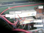
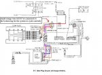
Does anybody have a good picture of their 24V postive terminal junction block and how its wired up? I pulled all the wires off today to clean the contacts and tried to keep the wires around their respective studs, but there were a few that I couldn't recall exactly (a small red wire, didn't have time to trace it but believe it runs to GEN2, a blue wire, and 2 small orange wires) They all had fusible links on them. I checked the TM wiring diagrams and couldn't find some of these (namely, the blue wire and the 2 orange wires) I checked some of the pictures in the instructions for the Roscommon 12V conversion and sure enough, orange and blue wires. ???? I reattched all the wires to where I knew or thought I knew, where they went and started the truck up just to be sure with no problems. Am I just worrying too much? Does it really matter where these wires attach as long as they're getting voltage?
 

Warthog

Moderator
Super Moderator
Steel Soldiers Supporter
13,775
227
63
Location
OKC, OK
Doesn't really matter which terminal you put the on as it is all 24v on each lug. I'll post a pic tomorrow

You have to look at all the diagrams to find all the wires
 

idM1028

New member
429
1
0
Location
Somewhere in Nebraska
OK thanks. Already checked and double checked all the wiring diagrams in the -20 that included the 24V block (I had all of them when I was working on the truck) No orange or blue wires (The blue wire in question does not run to the resistor bank) I thought they might have run to to the GP relay, but the wiring diagram shows all orange and blue wires on that running to either the glow plugs or the GP controller. The only reason I ask is even with the -20 and the wiring diagrams it still feels like I'm playing whack-a-mole with the electrical system.
 

idM1028

New member
429
1
0
Location
Somewhere in Nebraska
OK thanks for the pics! Yep, those are the orange and blue wires from the GP relay (in the wiring diagram at least). I know there's 24V running through the GP relay since I popped the fuse in my circuit tester the other day on it. The voltmeter confirmed: 24 volts. Only reason I didn't trace the wires of the junction block was I was running of time (daylight?) and well. . . I just really hate tracing wires.
 
Last edited:

Warthog

Moderator
Super Moderator
Steel Soldiers Supporter
13,775
227
63
Location
OKC, OK
You should be stepping down to 12v through the resister before hitting the GP relay. 24v will fry your plugs.
Partially right.

In a stock system and with the truck off 24v will at the GP relay terminal. When the GP system is energized, the combination of the Resistor pack and the glowplugs causes the voltage drop to 12v.

If one glowplug is bad, the voltage will increase a little. If a second goes bad the voltage inceases more and so on. Finally the last "good" glowplug will get the full 24v and die a painfull death.

Thanks for posting my Terminal Block picture. I was just getting ready to post it and you beat me to it.
 
Top
AdBlock Detected

We get it, advertisements are annoying!

Sure, ad-blocking software does a great job at blocking ads, but it also blocks useful features of our website like our supporting vendors. Their ads help keep Steel Soldiers going. Please consider disabling your ad blockers for the site. Thanks!

I've Disabled AdBlock
No Thanks