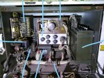
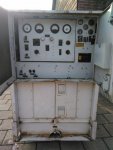
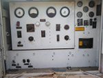
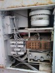
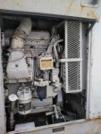
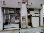
The "Emergency Switch". The switch under the red switch guard. There are a few safety circuits in the set. When they turn on, you can not put out power, or keep the set running. They are there to protect the gen set from killing someone, or destroying itself. BUT, In a war time environment, sometimes safety takes second place to survival. If the gen set will not run, your Missile System will not function. If the missile system will not function, the bad guys will kill you. So the option is there to engage the emergency switch, and walk away for the gen set. It will run until it uses all its fuel, or destroys itself.
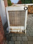
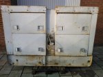
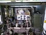
This is the 30 KW. I did not have a lot of experience with this model. But attached is your picture, with numbers written next to the sides.
1. Frequency Transducer. Converts 120 VAC signal to DC, and powers the Hertz Meter.
2.Safety relay. Not sure what.
3. LMU. Load Measuring Unit. Measures the load output, for Parallel operations.
4. This is probably a 500 Ohm resister, for the Air Box Solenoid circuit. When you shut the set off, the Air box should close up, and let no more air into the engine. It is also in the safety circuit. If a safety tells the gen set to shut down, then the Air box shuts off air and stops the engine.
5.The electric governor.
6. This is the AC Volt Regulator.
7. The black things on the box may be relays, or may be electrical tubes covered by aluminum tube covers. If so, this is part of the AC Volt Reg.
8. This is the Thermal Watt Converter. It collects AC signals, converts them to DC signals, to be read by the Percent of load meter and Power meter.
I can not see the switch you asked about, but most of the old sets had a manual excitation switch, to light off the main gen in case it did not happen automatically.
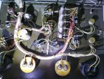
The two pots, (rheostats) on the left side could be to adjust the Over/Under box.
Since the numbers did not get copied, the #1 is the line that5 goes to the left. The #2 is the line in the bottom left corner. And so on, in a CCW fashion.
