• Steel Soldiers now has a few new forums, read more about it at: New Munitions Forums!

  • Microsoft MSN, Live, Hotmail, Outlook email users may not be receiving emails. We are working to resolve this issue. Please add support@steelsoldiers.com to your trusted contacts.


Rear Level Wind Servicing Tips

zebedee

conceptualizer at large
Steel Soldiers Supporter
1,605
661
113
Location
Central NY
Bench Servicing Tips. (All Numbers are relative to the Parts Diag {open seperate window from TM section of forum if pic too small}):

Rear Winch Levelwind Parts.jpg

Note EDITS in YELLOW when re-visiting thread.

Servicing is required if any of the grease fittings are blocked and/or any of the bearings, rollers or cable sheave wheel are siezed. Some of this can be done on the vehicle, however if removal/full servicing is required/chosen (blasting/painting etc.) here are my tips...

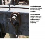
1/ Cable Guard #3 removed whilst on vehicle - slacken cable and pull loop aside.

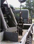
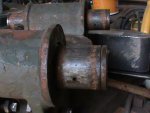
2/ Back off 4 number trolley retaining bolts #25, lift level wind complete from track. NB. Very Heavy.

3/ Locate and remove all grease fittings #7 x 7 number AND #26. Item #26 is a 2 part, 90 deg fitting (not found on all front winch level winds - see alternative thread for modification).

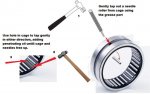
4/ Generally, there is enough mass in the complete levelwind that free disassembly can be done with suitable support and correct/appropriate drifts and sizeable hammers. Be carefull - heavy components are finger hungry.

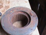
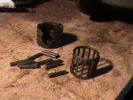
5/ Either trolley rollers #21 x 4 or cable wheel Sheave #30 would then be removed.

6/ Remove snap rings [circlips] - (may be seized in groove. Use snap ring pliers to open 'ears' then tap radially around groove before trying to) lift out of groove and pull off shaft x 2 in #15 or #11.

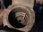
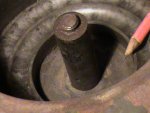
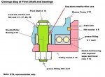
7/ For #30 removal, locate ONE NUMBER Sheave shaft pin (#7 in pic 2 from TM' 34-2 maintenance)
Rear Winch Levelwind - 1.jpg
tap or press sheave shaft #11 from Sheave frame #10 in direction of pin (#7 in pic 2)

...........................................................................................................................................
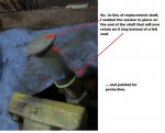
CLEAN AND INSPECT bearing surfaces of shafts for pitting. If really damaged - trolley wheel shafts can be pressed out and replaced - if part available.
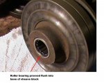
CLEAN AND INSPECT Roller bearings for operation. Subject to your expected use of rear winch, decide if freeing up and re-lubeing is adequate for needle rollers or that replacement is reqd. See post #7 for Needle Roller Bearing Disassembly/Servicing.

FELT WASHERS: can be "laminated" by cutting 'washers' for #19 or"strips" wound lengthwise for #8 - from sheet felt - available at fabric stores (Wally World etc).
...........................................................................................................................................

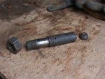
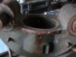
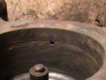
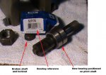
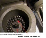
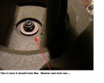
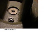
8/ Removal of Sheave frame #10 from trolley frame #15, check that nut #29 is inplace (mine was corroded and broken off of the pivot shaft #16 See pic 1 post #4). Shaft will have to be repaired or replaced once needle bearing #12 has been serviced as shaft will NOT fall out of base of trolley. This statement is now corrected as there is a shoulder for the shaft to sit on and the larger, lower nut, to draw up against. See diag post # 8 - (Mine was held inplace by siezed shaft/hard grease).

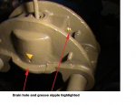
EDIT. TYPICAL REASON FOR FAILURE/CORROSION is blocking of 2 drain holes in sides of trolley frame #15, may have been painted over! Located approximately above felt washer #8 in sheave frame #10.


continued later.............
 
Last edited:

zebedee

conceptualizer at large
Steel Soldiers Supporter
1,605
661
113
Location
Central NY
Pics will be added to thread as it developes - but please note YELLOW edits of post #1 (assuming that I can still edit...) to basic proceedure or newer post as necessary.

I an considering placement of rubber 'O' ring under washer #28.....

I will be painting all grease fittings yellow for future location when on vehicle, also, I will be putting some yellow highlighting - triangle/arrow or similar, to ID drainage holes in #15...... not to be confused with yellow edits!!!!
 
Last edited:

zebedee

conceptualizer at large
Steel Soldiers Supporter
1,605
661
113
Location
Central NY
Tips - continued + pics

OK - good news/bad news on the broken pivot shaft #16: No luck yet on finding a replacement however on closer inspection of cleaned parts and test reassembly - there is a shoulder on the shaft that draws tight the shaft with the large nut on the bottom #17, so NOT replacing the shaft and using as is WITHOUT nut #29 will not create operation failure of the sheave etc. All it will mean is that washer/seal #'s 27&28 not being there could allow moisture to enter the bearing. To combat this - whilst awaiting replacement of shaft down the road, I plan on making a canvas cover to protect the whole levelwind and ALL it's water traps and bearings. JT be on notice for delivery of canvas pattern! 8)

Next stresser was removal of bearing #12. This is a plain roller without an inner race - just the outer race, cage and rollers. This is fitted into the base of the Sheave frame #10 and pressed up towards a shoulder in the frame base. (The "towards" is note worthy - more later) There is almost nothing to drift against from the top of the frame - WHICH has those great big sheave "ears" which hold the sheave shaft #11. This means there is limited access for a long drift to get down behind the bearing.
The TM calls for the use of an arbour press but without an exactly sized press shaft to push on ALL of the rollers (as that is all that sticks out - I was too keen for dissassembly and jumped that step!) I was forced destroy the bearing when the rollers started to fall out, then other rollers in the cage broke the bottom lip of the outer race and , well, pic 7 doesn't lie....

With no exposed edge it is impossible to drift out the outer race and so I was forced to burn it out. NB. There is a little space above the race, before the shoulder ("towards"), which could be used if a drift was made with a 'toe' or lip to possible catch the top of the race. Unfortunately for me - I had already closed this gap when trying to 'free' the race a little.

Bearing info - 1 3/8"OD, 7/8" ID and 1" long - so it should be easily found ....... more on that when I have sourced it.

The shiny surface on the shaft # 16 is not for the bearing but is ALMOST an 'interference' fit in the sheave frame #10. The bearing surface was the bigger dia next to the shiny part and was a little corroded but will clean and be serviceable until replaced. Since this bearing only slowly oscillates 70 - 80 degrees as the sheave follows the laying of the rope across the winch drum - it is not a high speed precision thing.

***************************************************

Pressing of the trolley roller bearings #20 from the rollers #21 is easily achieved with a press.
One of the shafts in the trolley frame #15 was pitted more than the others and all were seized with 'dry' grease but again - this simply rolls back and forth across the frame as the cable lays up on the drum so I am not concerned about perfection of the bearing surfaces so long as the bearings work and stay lubed.


Pic 1/ Pivot shaft #16 with broken top and small nut to right.
Pic 2/ Trolley frame #15 showing large (pencil sized) grease pathway. There is a second one opposite.
Pic 3/ Trolley frame showing two drain holes.
Pic 4/ Trolley roller #21 with hard grease/seized roller bearing.
Pic 5/ Trolley frame roller shafts with some corrosion/pitting and grease pathway.
Pic 6/ Pivot shaft dry-fitted to trolley frame. Note grease port for shaft needle bearing.
Pic 7/ Oooops. ... but no damage to base of sheave frame #10
 

Attachments

Last edited:

zebedee

conceptualizer at large
Steel Soldiers Supporter
1,605
661
113
Location
Central NY
Ordered pivot shaft bearing from Fastenal today. Around $25 ea. I ordered a spare in-case anyone else needs one and doesn't have access to a local store.

Don't even bother with NAPA - their bearing books don't go that small.


Added captions to pics in post #4. Was in the middle of doing that when a storm went over and I lost coms.
 
Last edited:

zebedee

conceptualizer at large
Steel Soldiers Supporter
1,605
661
113
Location
Central NY
Corrosion in Trolley Frame - Blocked Drain Holes

Forgot to add this pic showing the corrosion to the inner bore of the trolley frame due to blocked drain holes. Potentially this could be too much grease being pumped into the ball bearings below, forced up past the felt seal.

It might be worth reaming these holes out a little larger.

Pic also shows broken pivot shaft - missing most of small thread, seal, washer and nut.
 

Attachments

Last edited:

zebedee

conceptualizer at large
Steel Soldiers Supporter
1,605
661
113
Location
Central NY
Needle Roller Bearing Restoration - Trolley Rollers #20

Yes - this is possible and will save megga bucks and is appropriate for this situation as the trolley rollers #21 are not exactly rotating at thousands of rpm. With a 300' recovery, they may trundle back and forth a whopping 4 times across the track frame.


2 of the 4 trolley rollers were seized and somewhat rusty when I removed them. After soaking in cleaning fluid for a day or so, they still did not free up any.

So, taking a small pin punch, access the back of the cage and a roller through the grease port in the middle of the outer race outside. Gently tap a needle roller out of the race.
With the bearing outer race held in a vice (CAUTION not to over tighten and break it) and the gap from the removed needle at the bottom, you can gently alternate taps on either side of the cage to free up the remaining needles and cage.
Plenty of penetrating oil or washing (parts washer fluid) will assist.

As the cage begins to move, gently work it back and forth until all the crud can be washed out. But expect to go through a few examination gloves as they tend to get sucked between the rollers and cage! Use a rag in between them.

If individual needles are rusty, probably all the ones on the bottom when the winch wasn't being used, these can be aligned with the grease hole and tapped out for individual cleaning/smoothing/polishing as necessary. Pitting is ok in this application, but you do not want rust lumps/scale.
If you damage/bend the cage whilst removing the needles, then go ahead and remove all the needles by this method - then the cage will come out and can be reshaped.

Grease in the outer race will keep the needles inplace for reassembly, then regrease once all needles are in the cage, install and grease again with grease nipple to ensure evidence of grease getting through all passageways.
 

Attachments

Last edited:

zebedee

conceptualizer at large
Steel Soldiers Supporter
1,605
661
113
Location
Central NY
Here is a diagram of the inter-relationships of the parts, inc seals and bearings for the trolley frame/sheave frame connection. Also shows, from Post #4, the "Towards" reference relating to removal of the needle roller bearing.

NB. There is a machined recess that the washer #28 sits in, which will retain water but I forgot that when doing this drawing. See post #12 for possible remedy.
 

Attachments

Last edited:

zebedee

conceptualizer at large
Steel Soldiers Supporter
1,605
661
113
Location
Central NY
Reassembly time

Finally got the new pivot shaft bearing, however no available pivot shaft so I had to improvise...

Bearing was a SJ7174 from Fastenall. Came to around $28 with shipping from BFE - took so dang long.
Dims if that reference isn't any help: 7/8" ID, 1 3/8" OD x 1" long.

I have a spare if anyone needs one and can't find it online...

I had also stuck the pivot shaft in the lathe and polished up the corroded area that the needle rollers run on after the trial fit of the new bearing felt a whisker tight - again, we are not talking Formula 1 main bearings here.
 

Attachments

Last edited:

Jeepsinker

Well-known member
5,341
329
83
Location
Dry Creek, Louisiana
I'm glad you are doing this with a how-to. My rear level wind doesn't work unless you stand up top and kick it back and forth, which.... Is a bit dangerous...
 

zebedee

conceptualizer at large
Steel Soldiers Supporter
1,605
661
113
Location
Central NY
Jeepsinker - you are welcome, I actually enjoy all the picture manipulation and diagram stuff.

OK - in pic 5 and 6 of last post (#10), that is still a large recess where the washer (and nut that should be there) is, to hold water and it's below the drain holes... I am thinking about filling that whole machined out depression with caulk, similar to the vertical rollers in the rear fairlead (need to find that thread too!!) ....trouble is the washer, nut or in my case the weld bump and shaft have to turn so careful smearing of grease/squirt of silicone spray would be prudent.

Maybe I can find some kind of a rubberised bung, blind grommet, plug thing that will fit....


What about someone with a 3D printer!!!!!! I can do a drawing.....
 
Last edited:

1954 COE

Member
56
2
8
Location
El Paso, Tx
Great write up. It will be useful when I service mine. On your last conversation regarding the large recess, two suggestions if applicable.
Since you welded the washer in place of the nut tightened to the threaded shaft, how about seeing if you can increase the diameter of the
washer to completely fill the recess in whether it is used with or without the lock nut. Second suggestion would be to size a shaft seal
by dimensions with the fixed dimension being the O.D. of the recess and increasing or reducing the size and thickness of the washer
depending on what bore sizes would be available in the corresponding cross section of the shaft seal. Could be a lot of choices.
Because of what you have determined to be a probable failure point, this modification should be just that, going forward and applicable
to all of the level winds in the TM's. IMHO.
 

zebedee

conceptualizer at large
Steel Soldiers Supporter
1,605
661
113
Location
Central NY
It's been a while, but I decided to finish the rear level wind rebuild....

Part one - Trolley wheels.


20170225_143818.jpgTurned up "cookie cutter" for felt washers...

20170225_144003.jpgCut out 32 washers, that's 4 per original 1.
I bought sheet felt from WallyWorld. Similarly any craft store. Use small hammer just like doing external shape with sheet gasket. (Ballpien used for internal radii and bolt holes)

20170225_154310.jpgStart rebuild. Clean paint off of axle. Thrust washer on greased axle. Make sure to fill recess in cast body where axle goes in before sliding on thrust washer.

20170225_155616.jpgInner 4 felt washers. Lightly grease these as you go.

20170225_154812.jpgPress needle bearing into trolley roller, don't try to hammer bearing - outer race will probably crack. I think I used an 1 5/8" x 3/4" drive socket to ALMOST match diameter. (You don't want to get the socket stuck in wheel!)
20170225_155135.jpgcenter bearing in trolley roller to allow even space for felt washers on both sides

20170225_160331 (2).jpgfit grease nipple and pump grease until it shows

20170225_160404.jpgUse strap wrench to free tight roller - paint etc., may initially resist turning by hand.

20170225_160756.jpg fit outer 4 felt washers into space next to bearing, lightly greasing as you go.

20170225_161033.jpgOuter washer and cir-clip. Tap cir-clip with a small punch to ensure it goes around the groove.

Finally finish greasing and turning wheel several times.


Rinse and repeat three more times!
 
Last edited:

zebedee

conceptualizer at large
Steel Soldiers Supporter
1,605
661
113
Location
Central NY
Felt washers form craft sheet.

Making the felt washers: Cookie cutter for outside diameter, then the inside 'hole' was hand cut with scissors, by folding the washer in half and carefully following what looked like the approximate thickness.
I did try a few by folding it into quarters, but that was too fiddley, trying to keep the 4 layers together.
Any imperfections in the shape won't really matter as the felt will 'move' into the space, compress etc., but still do it's job of retaining some of the grease and reducing ingress of moisture/grime. Did some one say "regular greasing"???

20170225_161237.jpg20170225_161353.jpg
 
Last edited:

zebedee

conceptualizer at large
Steel Soldiers Supporter
1,605
661
113
Location
Central NY
Part Two - Sheave Swivel.

20170226_171920.jpgGrease double ball race on underside of swivel sheave frame bearing ring
20170226_171916.jpgGrease double row of ball bearings in lower bearing ring in frame assembly
20170226_174040.jpgCut long strips of felt, ~1/4" wide. Wrap around groove in sheave frame. Lightly grease each circumfrence so that it sticks inplace. I used about 6', two strips from the 3' wide sheet that I got from the craft section of wallyworld

20170226_175319.jpgDue to modification/repair detailed earlier, install O ring and hand cut felt washer to top end of shouldered shaft
20170226_174433.jpgIntroduce swivel sheave frame into trolley assembly, carefully pack strip of felt if it gets caught on edge.
20170226_174443.jpgFit castellated nut on bottom of shouldered shaft, install lowest grease nipple and fill with grease.
20170226_175315.jpgbarely visible in this pic are the drain holes in the trolley frame assembly sides. I'll probably ream these two holes out a little larger to promote better drainage. This should probably have been done before everything was cleaned, painted and reassembled!
20170226_182132.jpgPress bearing outer race and cage into pulley wheel
20170226_182422.jpgensure it is centered to accept shouldered washer either side.
20170226_183927.jpgIntroduce pulley wheel to sheave frame. Ensure that two shouldered washers have larger shoulder out - this centers the bronze thrust washers. When fitting the bronze thrust washers, put the dimples towards the shouldered washers.
Insert the sheave pulley straight shaft into one side of the sheave frame, align the pulley wheel and washers before sending the shaft all the way through.
 
Last edited:

SLOrazorsedge

Member
415
5
18
Location
San Luis Obispo, Ca
Nice tutorial brother. Question, my fairlead roller (M936A1) seems to be draining gear lube on both ends of the roller. There appears to be a hex plug up on top for filling the roller reservoir. It just just doesn't make sense that the roller would be filled with gear lube. What can you advise?
 

73m819

Rock = older than dirt , GA. MAFIA , Dirty
Steel Soldiers Supporter
In Memorial
12,196
314
0
Location
gainesville, ga.
NOT gear lube but grease with a bit of water and rust, this is a good thing, just KEEP greasing, you can not over grease , the plugs are for GREASE FITTINGS, pump it till grease comes out a end/ends.
 

zebedee

conceptualizer at large
Steel Soldiers Supporter
1,605
661
113
Location
Central NY
Not totally sure what you are referring to... "roller reservoir"?
All my fairlead rollers were packed with grease, quite the volume.

Question, my fairlead roller (M936A1) seems to be draining gear lube on both ends of the roller. There appears to be a hex plug up on top for filling the roller reservoir. It just just doesn't make sense that the roller would be filled with gear lube. What can you advise?
If we are talking the same thing, sounds like "someone" got tired of pumping grease and decided to 'pour' lube in instead. From memory, I am thinking there are no proper oil seals anywhere.


Got any pics of your situation??


Associated thread:
http://www.steelsoldiers.com/showthread.php?97456-M816-rear-winch-roller-drain&highlight=


WOW - I can't believe that KGR types faster than me!!!!!!
 
Last edited:
Top
AdBlock Detected

We get it, advertisements are annoying!

Sure, ad-blocking software does a great job at blocking ads, but it also blocks useful features of our website like our supporting vendors. Their ads help keep Steel Soldiers going. Please consider disabling your ad blockers for the site. Thanks!

I've Disabled AdBlock
No Thanks