• Steel Soldiers now has a few new forums, read more about it at: New Munitions Forums!

  • Microsoft MSN, Live, Hotmail, Outlook email users may not be receiving emails. We are working to resolve this issue. Please add support@steelsoldiers.com to your trusted contacts.

"Rescued" M816 Wrecker

red

Active member
1,988
22
38
Location
Eagle Mountain/Utah
Had the hood up today, not for engine work just to finish up installing the backing plate/air fittings for the brake pedal.

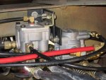
Started off by swapping out the fittings and plugging off the unnecessary ports on the middle axle air cans. The one with my finger on it is for the service brake side. All the fittings here are 1/2" JIC and the hoses will be the heavy duty hose just like the front axle.

IMG_20170510_115028664.jpg IMG_20170510_115823027.jpg IMG_20170510_115827597.jpg IMG_20170510_122208120.jpg


Then the service only air can

IMG_20170510_123959927.jpg


With the middle axle now ready for it's hoses (valves aint here yet) went to the rear air tank and finished up installing it's fittings

IMG_20170510_140204683.jpg

And a better idea of its mounting location, it will sit flush with the bottom of the frame. Have to make the mounting brackets for it. There are a total of 5 connections on the 'new' rear tank. Supply, drain/return, 1 for the R14 emergency brake supply, 2 for the R12 service brake supplies (1 per R12 valve).


IMG_20170510_140148854.jpg
 

Another Ahab

Well-known member
17,841
4,199
113
Location
Alexandria, VA
And a better idea of its mounting location, it will sit flush with the bottom of the frame. Have to make the mounting brackets for it. There are a total of 5 connections on the 'new' rear tank. Supply, drain/return, 1 for the R14 emergency brake supply, 2 for the R12 service brake supplies (1 per R12 valve).


View attachment 679942
Hey, Mr red, I'm not picking up on the drain valve on that underslung drain/ return connection.

I'm likely missing something. How does the tank get drained there?
 
Last edited:

red

Active member
1,988
22
38
Location
Eagle Mountain/Utah
Hey, Mr red, I'm not picking up on the drain valve on that underslung drain/ return connection.

I'm likely missing something. How does the tank get drained there?
Mr, I'm no sir I work for a living..... wait, not so much right now hahaha.

This generation 5 ton, m809 series, only has 1 drain valve for the air tanks. Located underneath the driver step.

That low drain/return connection will be plumbed into the stock tanks drain valve. The rear tank sits higher than the stock drain valve, so when the valve is opened then the air/water will flow through the lower fitting on the rear tank and drain out.
 

red

Active member
1,988
22
38
Location
Eagle Mountain/Utah
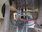
The 3 valves for the rear axles came in last week and got around to installing them today.

IMG_20170515_115051920_HDR.jpg


Plan is to mount them up nice and high, keep them protected while still accessible. Naturally there was no great mounting location or really usable holes (and don't want to drill through the frame much) so had to figure out a mounting plate for the 2 R12 valves and 1 R14 valve. Decided to take the engine side cover panel from the m51a2 I've had for sale for the last year and cut it up.

IMG_20170515_123435700.jpg


Test layout, decided on the second layout for easier access to the fittings and less cutting required.

IMG_20170515_124016289.jpg IMG_20170515_152716663.jpg IMG_20170515_152734903.jpg


For now it only has the front hanger but think I'm going to add a second hanger to the rear for a stronger mount.

Mounted it to the cross member directly over the trunion and offset to the passenger side to clear the driveshaft between the rear axles. Can't realistically go higher because of the crane components. Something would have to go over the rear axles to hit the valves in this location so other than a driveshaft failure it's a very well protected spot.

IMG_20170515_153340152.jpg IMG_20170515_153358336.jpg


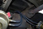
Then came some hose routing, cutting, and installing ends. Granted this hose is extremely durable I'm still trying to protect it as best as realistically possible. Built and figured out the routing for the 3 hoses coming from the driver side hub. They will go up/over the top of the pinion housing, then run along the inside edge of the upper dog bone. The passenger side will run up along the inside edge of the upper dog bone as well.

IMG_20170515_155308484.jpg IMG_20170515_155315388.jpg IMG_20170515_155326328.jpg IMG_20170515_170015305.jpg IMG_20170515_170021803.jpg


3 hoses required per hub on the rear axles, total of 6 hoses per axle. Driver side hoses are 5 1/2ft long each, passenger side hoses will be about 3ft long ish.
 

MyothersanM1

19K M1 Armor Crewman
Steel Soldiers Supporter
1,954
402
68
Location
Culver City, CA
I tucked mine up against the crossmember directly above the trunnion. I fabricated a special bracket out of some 1/4" steel angle then drilled and mounted the bracket to the crossmember. Both the R-12 service relay and the SR-7 spring brake modulating valve were bolted to the bracket just low enough so the hoses would clear the crossmember. I oriented all my hose fittings to run on the horizontal with the hoses routing directly up over the differential housings.
IMG_0332.jpgIMG_0347.jpg

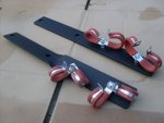
Some hose stand-off brackets were fabbed up with hose clamps. These keep the hoses in check side to side and allow them to follow the axle articulation. The brackets bolt right over the differential top cover plates using the existing bolt holes. Longer bolts were required and some stacked washers for a little stand off.

SDC12620.jpgDSC_0013.jpgDSC_0014.jpgDSC_0016.jpgDSC_0012.jpg
 

red

Active member
1,988
22
38
Location
Eagle Mountain/Utah
Will be making a similar hose guide bracket for each rear axle, haven't gotten to it yet.

Today was more plumbing. Started off by making the 3 hoses needed for the middle axle passenger side hub, about 3ft long each. Didn't realize the pic came out blurry. Ran the hose for the emergency brake signal as well.

IMG_20170522_173031290.jpg

IMG_20170522_173041974.jpg

All that's left for the middle axle is the hose guides and running the supply hose from the 3rd air tank to the r14 (emergency) and that axle's r12 (service) brake valves.


Then sat in the cab for a few minutes, figuring out where to drill lots of holes through the firewall and into the dash. Plan is to make the cab easier to remove when needed so working on consolidating all the air lines and wires into 1 location. Eventually will get the wiring setup on a few bulkhead plugs and the air lines are currently going through that modification.

So drilled 5 holes for 3/8" airline bulkhead fittings. Location is large enough for the rest of the air line fittings to be routed there as needed.

IMG_20170522_153947618.jpg IMG_20170522_163943699.jpg


Then plumbed in the PP7 valve (emergency brake release) and rerouted the plumbing for the front axle disconnect switch. Need some more 3/8" hose to finish the plumbing for both inside the cab and will clean up the hose routing at that point.

IMG_20170522_170310035.jpg


Finally decided to use the area to the right side of the gauge cluster for the controls. PP7, trailer brake valve, front axle disconnect switch, and winch brake switch will all go in this area.

IMG_20170522_170110307_TOP.jpg


Getting very close to being mobile again. Little more plumbing, mount the air tank, and new wheel studs for the middle axle will get it mobile with 4 brakes.
 
Last edited:

red

Active member
1,988
22
38
Location
Eagle Mountain/Utah
That's sure going to be a lot of connections and fittings to leak test! hehe
More than it had before. On the bright side though if there is a leak, they are easy to access haha.


Picked up and installed new studs for the middle axle passenger side hub. Inner bearing repacked with new grease and the studs driven in

IMG_20170525_134739543_HDR.jpg


These are much heavier than the older hub/drum setup and I follow the mindset of "work smarter not harder". So since I currently don't have a small manual winch (come along), rigged up a ratchet strap.

IMG_20170525_140507712_HDR.jpg IMG_20170525_140621220_HDR.jpg


Then with those in place and the strap removed went ahead and greased up the outer bearing, seal, then torqued everything down and installed the wheel.

IMG_20170525_161915184_HDR.jpg IMG_20170525_162143473.jpg


Which created a unexpected outcome, a wider stance. About 5" wider total including the other side.

IMG_20170525_161932373_HDR.jpg
 

red

Active member
1,988
22
38
Location
Eagle Mountain/Utah
So you mean 5" overall, right (2-1/2" wider on each side x 2)?

I'm remembering that there's some federal width limit (8 foot?). That's still legal isn't it?
yep, 5" overall (roughly). Still within the legal width. This stance is about 3" wider overall than the factory duals were. The tires are still narrower than the outrigger feet are when packed up/stowed.
 

red

Active member
1,988
22
38
Location
Eagle Mountain/Utah
Pretty much finished up the plumbing today.

Started off my mounting and taking care of the vent line for the PP7 valve. Plumbing for the front axle disconnect is setup as well, just need to decide exactly where on the dash it will be mounted.

IMG_20170530_174126299_HDR.jpg


Plumbing at the engine side of the firewall. The 3/8" hose going from the treadle to the QR1 valve on the front axle is black instead of blue.

IMG_20170530_174559717.jpg


Plumbing for the air supply from the rear tank to the R12/R14 valves.

IMG_20170530_163916351.jpg IMG_20170530_163922911.jpg IMG_20170530_163929613.jpg


Hung the tank by a ratchet strap for now. Still need to make its proper mounting straps.

IMG_20170530_171447642.jpg IMG_20170530_171452148_HDR.jpg


Last piece of plumbing (that I can currently think of) is tying in the drain hose. Need another T fitting for that but should have it finished up tomorrow. After the pic decided to upgrade it to the heavier duty hose since it hangs low, just under the driver side step.

IMG_20170530_171106489.jpg


Wheel studs/hub assembly for the driver side middle axle and the last little bit of plumbing is planned for tomorrow if the weather cooperates. 3rd axle will not be touched until after July 4th most likely.
 

red

Active member
1,988
22
38
Location
Eagle Mountain/Utah
Finished up the plumbing, hub assembly on driver side middle axle and then went for a quick stroll around the lot. First time it's moved since just before Thanksgiving. Tested out both the service brakes and the emergency brake, good function from both sets. Need to secure the hoses before it's actually "mobile" for short distance trips.

IMG_20170531_200749768.jpg


Can see in this picture how much the tires stick out now on the middle axle, 3rd axle will be the same way when I get around to its conversion.

IMG_20170531_200739863.jpg
 

red

Active member
1,988
22
38
Location
Eagle Mountain/Utah
Hasn't even been "mobile" for 24 hours yet and already putting it to use.

received_455208078159645.jpg received_455208064826313.jpg received_455208058159647.jpg received_455208034826316.jpg received_455208011492985.jpg received_455208008159652.jpg IMG_20170601_170536540.jpg IMG_20170601_173725978_HDR.jpg


The dump bed sub frame/pump are bound for other projects of mine. The remains of the old military ambulance (red metal) will be used to make the tool box for the m103a2.

Considering the brakes are only on 2 axles they are working well. Even still, it's most likely one of only 2 trips that it will make before the 3rd axle is converted. Was also able to split shift using the tcase today which is a nice change.
 

red

Active member
1,988
22
38
Location
Eagle Mountain/Utah
Did some more work with the wrecker today. Unloaded the other dump bed sub frame/components along with the scrap metal from the m103a2 trailer. Then moved a generator from a friends pickup to his trailer.

IMG_20170603_125155267_HDR.jpg IMG_20170603_125240841.jpg


Then hooked up and lifted the m51a2 remains, moved it over to the shop so we could work in the shade. Trying to sell the last of the big parts off of it before turning it into a trailer later this year.

IMG_20170603_150000374.jpg IMG_20170603_152529918_HDR.jpg


Even though the air brake conversion is only 3/4 done I have to admit, having a parking brake that actually holds the truck reliably is great!
 

red

Active member
1,988
22
38
Location
Eagle Mountain/Utah
nice work Red. Ive been busy lately and for some reason I haven't been getting the email updates from SS
Excuses excuses haha.

Wrecker has currently taken a back seat to project priority since it is mobile again. Sold the house back in Texas finally and bought a truck that is durable enough to survive my uses, 82 GMC 1 ton crew cab. Biggest problem for me with the truck is the total length because I have to park inside the garage. So lately and for the next few days I've been cutting down the wheelbase and the bed to about 5ft long. Decided to take the bed from the m103a2 and modify it for the pickup.

Wrecker mods will continue again in July. Might get the new synthetic cable on the crane before then.
 

red

Active member
1,988
22
38
Location
Eagle Mountain/Utah
Curious about those cables, red, are they UV-protected?

What I mean is, are they prone to weakening and damage while exposed to the sun on the drum?
UV rated but the sun still breaks down the synthetic cable over time. Plan is to make a cover for the crane to protect it when not in use and extend it's life. Synthetic cable became approved for cranes a few years ago. This is a test run for using synthetic on one of these trucks and I'm not using the currently strongest synthetic cable option either, still much stronger than the steel cable though.

Downsides to the synthetic:
UV breakdown
Higher cost
Easier to cut

Upsides to synthetic:
Stronger
Easier to repair in the field
Safer if it breaks
Safer to handle
Lighter (floats on water)

The 1/2" IWPS steel cable is rated for 20-21k breaking strength. Synthetic I'm going to is 27k, current strongest is 32k. So with the crane rigged to a 3 part line as it currently is that gives a safety factor of 3:1 with the steel cable. With 27k synthetic rating that provides a 4:1 safety factor and with the 32k rating that gives a 5:1 safety factor. Means that the synthetic cable will not be working as hard as the steel cable was when lifting stuff.
 
Top