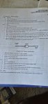
I looked back through titles trying to see if this has been addressed. The TM 9-6115-642-24
2-34.2 it says to test the resistors disconnect the battery cable then start testing each resistor. When I had checked them before I assumed they were in parallel with something and that's why they were 1 ohm. Then I read this and thought hmmm. Maybe they are bad. Then I checked my other gens. They all read 1 ohm on 10,11 and 12.
I do have a couple diodes that need to be replaced unfortunately but that's not what this is about. Am I missing a step? Is the TM just wrong? I usually assume you need to isolate resistors and other things unless you know what the reading should be. That or I need to replace a lot of resistors. Has this been discussed and I just didn't find it?