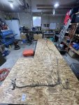
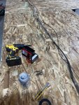
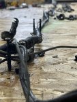
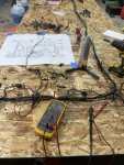
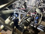
Ill start off with, I have a 1952 M37 that I purchased on a whim 3 years ago. From the time I bought it the electrical system was in shambles. I had no working lights at all, and every wire was labeled differently than the schematic with painters' tape, and half-baked splices all over the place. Those first couple months that I owned it I tried and tried to get some working lights and get everything labeled but the amount of crusty insulation causing shorts all over I ended up giving up on that project. I settled for one taillight wired directly to the brake light pressure switch to give me a brake light to make it street legal during daylight hours. I drove it like this for almost 3 years, until last fall when I decided enough was enough.
My intent with this post is to share some of the tips/tricks and issues I ran into when rebuilding my wiring harness from the ground up. It may take me a few days in between posts to get the pictures and some videos sorted and get write ups done. When I first started looking into doing this I searched and searched and found very little in the way of specifics on the harness other than some grainy photos of a harness laid out, and the various schematics posted online.
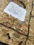
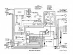
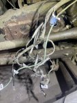
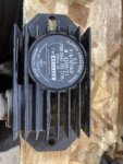
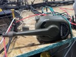
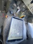
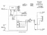
This first round will be about the condition of my wiring as I found it. It had from what I can tell, the original harness with Douglas connectors. Turn signals were added later with the wires ran along the main harness and had Packard connectors. It had a solid-state flasher PN:11613663, and turn signal switch PN: M62069/1-2 (11613632-1) installed. From what I can gather with some googling, This turn signal switch is an early version with the indicator bulb at the end of the lever instead of under the lever as most replacements with the same part number have. The light switch was that standard 3 lever switch, and the ignition switch was a replacement that had screw down terminals. I tested both the light switch and the turn signal switch based on a diagram I found on the M37 facebook group. The turn signal switch I did not have a schematic for so I made my best guess based on the main full harness schematic. I will attach those to this first post, as well as the edit I made to highlight just the turn signal legs as well as the edits for how the solid-state flasher should be wired.
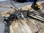
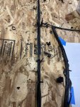
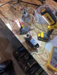
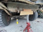
Prepping for this I spent the better part of a week and a full weekend tracing and verifying every wire I could before I started removing the harness. I started with tracing from the 3 lever switch using a pin saver on a long multimeter lead, having a multimeter with an audible indication of continuity is very helpful here unless you have someone else helping you. Thankfully the connections on the inside of the passenger side front fender were mostly intact giving me a decent starting point for the rear harness. Ill apologize I did not get many pictures of the rear harness removal, but ill add a few notes about it. It helps to have a tall jackstand to rest the fuel tank on. unless you cut the harness (I do not recommend since it will be harder to do the layout later) you will have to drop the rear of the fuel tank to get the connectors through the right rear of the frame/bed/bumper junction. After that the removal is straight forward, removing the retainer clips along the frame as you work your way to the front. It may be easier to pull it out from the rear after you clear that corner with the connectors. Taking off the floor pans on the passenger side floor may help with this as well.
Ill leave this as the first in this series, and try to get up one this weekend about rebuilding the rear harness.
My intent with this post is to share some of the tips/tricks and issues I ran into when rebuilding my wiring harness from the ground up. It may take me a few days in between posts to get the pictures and some videos sorted and get write ups done. When I first started looking into doing this I searched and searched and found very little in the way of specifics on the harness other than some grainy photos of a harness laid out, and the various schematics posted online.
This first round will be about the condition of my wiring as I found it. It had from what I can tell, the original harness with Douglas connectors. Turn signals were added later with the wires ran along the main harness and had Packard connectors. It had a solid-state flasher PN:11613663, and turn signal switch PN: M62069/1-2 (11613632-1) installed. From what I can gather with some googling, This turn signal switch is an early version with the indicator bulb at the end of the lever instead of under the lever as most replacements with the same part number have. The light switch was that standard 3 lever switch, and the ignition switch was a replacement that had screw down terminals. I tested both the light switch and the turn signal switch based on a diagram I found on the M37 facebook group. The turn signal switch I did not have a schematic for so I made my best guess based on the main full harness schematic. I will attach those to this first post, as well as the edit I made to highlight just the turn signal legs as well as the edits for how the solid-state flasher should be wired.
Prepping for this I spent the better part of a week and a full weekend tracing and verifying every wire I could before I started removing the harness. I started with tracing from the 3 lever switch using a pin saver on a long multimeter lead, having a multimeter with an audible indication of continuity is very helpful here unless you have someone else helping you. Thankfully the connections on the inside of the passenger side front fender were mostly intact giving me a decent starting point for the rear harness. Ill apologize I did not get many pictures of the rear harness removal, but ill add a few notes about it. It helps to have a tall jackstand to rest the fuel tank on. unless you cut the harness (I do not recommend since it will be harder to do the layout later) you will have to drop the rear of the fuel tank to get the connectors through the right rear of the frame/bed/bumper junction. After that the removal is straight forward, removing the retainer clips along the frame as you work your way to the front. It may be easier to pull it out from the rear after you clear that corner with the connectors. Taking off the floor pans on the passenger side floor may help with this as well.


Ill leave this as the first in this series, and try to get up one this weekend about rebuilding the rear harness.


