m4A1
New member
- 141
- 2
- 0
- Location
- California
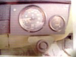
Does anyone know how the lug on back of the Alt #1 determines the rpm? I heard it is where the STE/ICE picks up the rpm and was wondering is there a way to rig a tack with it?
Steel Soldiers now has a few new forums, read more about it at: New Munitions Forums!


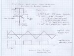
Ok, uber writeup time! First things first, a BIG thanks to Lee Swanger from www.thedieselpage.com for coming up with the circuit, I had no part in developing this one myself
Now, I know most of you are going to take one look at this circuit and look a bit like this -> but it is actually a pretty simple concept.
First things first, I should explain what exactly a transistor is. A transistor is basically two diodes connected together. Diodes are basically one way check valves for electrical current. They flow current like a bare wire in one direction, but allow very little current to flow through in the other direction. When you put the diode in so current flows through it, it is said to be forward biased, when it blocks flow, it is said to be reverse biased.
One side of the diode is called the cathode, and the other is called the anode, but when it comes to transistors, the cathode is the "N" junction, and the anode is the "P" junction. Depending on how the diodes are mated together in the transistor is called either a PNP or NPN transistor. The only difference is if the cathodes are connected together (PNP) or if the anodes are connected together (NPN).
Every transistor has three poles on it, one is called the collector, another the emitter and the third is the base. The collector and emitter are the ends of the diodes that are not connected together, and the base is the terminal that is attached to the connection between the other two ends of the diodes.
I won't get into why or how, but a transistor is capable of being in three basic modes. One is called cutoff, another is called saturation, and the third is called the active mode. When you operate a transistor in saturation or cutoff mode, it operates just like a switch, either allowing current to pass, or not(I'll let you guess which mode is which). When it is in active mode the transistor acts as an amplifier and increases the size of the input signal.
Now, since the stock engines speed sensor outputs the triangular looking signal, we want a way to clip the signal and convert it into a square wave which most gasoline tachometers use. To do this, we want to have some way to make the transistor output a 9 - 14 volt square signal when the sawtooth waveform is at one point in its cycle, and make it into a 0 volt signal at another point in it's cycle. What we do to pull this off is use the transistor as a tiny relay that is either on or off depending on the input signal.
Since I have not looked at the ESS signal on an oscillioscope myself, I can't say for sure exactly where in the signal the change happens, but what you see below should be accurate enough for our purposes.
Basically, when the sawtooth waveform goes positive, the base is given enough current to put the transistor into saturation, which closes the circuit and allows power to pass into the tachometer. When the sawtooth waveform goes negative, it opens the circuit and provides the sudden loss of voltage that the tachometer is looking for. Becuase the transistor is switched on at a certain point, the voltage of the input signal doesn't make any difference to the circuit's operation, just the frequency. Since the transistor is switching full battery power on and off, the tachometer gets the proper square wave signal it is looking for and displays the approriate engines speed based on that signal.
The resistor sizing changes how the transistor behaves, and when it will go into saturation / cutoff essentially setting conditioning the circuit to work with your V8 tachometer. The capacitator is used to clean the signal up for conversions so you can eliminate any spikes in ESS signal that could put the transistor into the wrong mode and make the tachometer read incorrectly.
If that made no sense, don't worry about it, just hook the circuit up the way you see it and enjoy! If you understand this stuff, and I made no sense, I apologize, just learned how to do this stuff a couple weeks ago at school
Has anyone ever figured this out? The diagram for this circuit refers to the california ESS signal for the sawtooth waveform. Does the J code 6.2 have a similar device? Has any one ever looked at pin E (the tach pin) on the ste/ice diag plug to see what is actually there?Found this over at ck5.com...
I hooked a multimeter up to mine and nothing showed. Not sure if it is not going to show anything or if mine is dead.Has anyone ever figured this out? The diagram for this circuit refers to the california ESS signal for the sawtooth waveform. Does the J code 6.2 have a similar device? Has any one ever looked at pin E (the tach pin) on the ste/ice diag plug to see what is actually there?
I would really like to use this old tach I have and make this work. That little circuit would cost next to nothing to put together.
")