• Steel Soldiers now has a few new forums, read more about it at: New Munitions Forums!

  • Microsoft MSN, Live, Hotmail, Outlook email users may not be receiving emails. We are working to resolve this issue. Please add support@steelsoldiers.com to your trusted contacts.


Tachometer testing

papakb

Well-known member
2,288
1,185
113
Location
San Jose, Ca
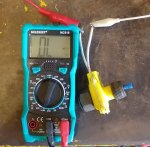
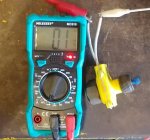
Does anyone know if there is a way to test the HMMWV tachs before installing them? Is there a bench test for them and the RPM sensor? Is this thing a Hall Effect sensor?

Thanks
 
Last edited:

Valor

Active member
185
192
43
Location
Apple Valley, Ca.
Does anyone know if there is a way to test the HMMWV tachs before installing them? Is there a banch test for them and the RPM sensor? Is this thing a Hall Effect sensor?

Thanks
Yes and yes!
 

Gamble

Well-known member
380
308
63
Location
Los Angeles, CA
It's funny you post this. I just sent my tachometer back because I couldn't get mine working either. Tried on both the Alternator 'AC' post and Ground as well as on the yellow transmission component behind the doghouse cover and no luck.
 

papakb

Well-known member
2,288
1,185
113
Location
San Jose, Ca
Valor, Are you looking for the same information? I think this system is one of the least understood additions to the HMMWV and I think there are an awful lot of people looking for this information. Those of you that retro'd a tach and it worked are lucky, let's find out what needs to be does when they get installed and don't work!

I have the 4 terminal tachometer and it's easy to give it 24 volts but what does the signal input from the RPM sensor look like? Can I use a square wave generator to trigger the tachometer? I've run the continuity checks from the sender leads to the tach and they're good. I have +27 volts on the input terminals. I've tried additional grounding and unplugging the RPM sender connection to the STE/ICE connector without success. It could just be a bad tach but I'd like to verify that before I go out and buy a replacement.

I believe it's the cannon plug tachometer that attaches to the alternator output. A similar beast with different problems.
 
Last edited:

Mogman

Moderator
Staff member
Moderator
Steel Soldiers Supporter
5,909
8,231
113
Location
Papalote, TX
Valor, Are you looking for the same information? I think this system is one of the least understood additions to the HMMWV and I think there are an awful lot of people looking for this information. Those of you that retro'd a tach and it worked are lucky, let's find out what needs to be does when they get installed and don't work!

I have the 4 terminal tachometer and it's easy to give it 24 volts but what does the signal input from the RPM sensor look like? Can I use a square wave generator to trigger the tachometer? I've run the continuity checks from the sender leads to the tach and they're good. I have +27 volts on the input terminals. I've tried additional grounding and unplugging the RPM sender connection to the STE/ICE connector without success. It could just be a bad tach but I'd like to verify that before I go out and buy a replacement.

I believe it's the cannon plug tachometer that attaches to the alternator output. A similar beast with different problems.
The "yellow" sending unit is simply a reed switch with two magnets so it gives one open and closure per crankshaft revolution and would look like a square wave, the other or "black" sending unit is an inductive pickup so it actually generates a voltage that would look like a sine wave, 86 says he has tried and both work.
 

Retiredwarhorses

Well-known member
Steel Soldiers Supporter
4,257
3,863
113
Location
Brentwood, Calif
There are only 2 Tach’s that work on this truck from the military, the cannon plug version “ECV” that’s for 200 and 400amp, and the 4 screw version that is used on A2 and below trucks, these get its signal from the Tach drive used for ste/ice, I’ve installed many of them with zero problem. The cannon plug version also works on Any model truck with a 200amp as the signal comes from the generator.
 

Valor

Active member
185
192
43
Location
Apple Valley, Ca.
Valor, Are you looking for the same information? I think this system is one of the least understood additions to the HMMWV and I think there are an awful lot of people looking for this information. Those of you that retro'd a tach and it worked are lucky, let's find out what needs to be does when they get installed and don't work!

I have the 4 terminal tachometer and it's easy to give it 24 volts but what does the signal input from the RPM sensor look like? Can I use a square wave generator to trigger the tachometer? I've run the continuity checks from the sender leads to the tach and they're good. I have +27 volts on the input terminals. I've tried additional grounding and unplugging the RPM sender connection to the STE/ICE connector without success. It could just be a bad tach but I'd like to verify that before I go out and buy a replacement.

I believe it's the cannon plug tachometer that attaches to the alternator output. A similar beast with different problems.
I have mine working. I have the 4 terminal tach in a civy suburban and it works great. The signal is a sawtooth wave. You can get a square wave generator and hook it up to the tack and see it work. I did that. Make sure your rpm sending unit is working, use the drill test with voltmeter. Check all wiring. Good luck.
 

Mogman

Moderator
Staff member
Moderator
Steel Soldiers Supporter
5,909
8,231
113
Location
Papalote, TX
I have mine working. I have the 4 terminal tach in a civy suburban and it works great. The signal is a sawtooth wave. You can get a square wave generator and hook it up to the tack and see it work. I did that. Make sure your rpm sending unit is working, use the drill test with voltmeter. Check all wiring. Good luck.
The most common "yellow" sending unit as I have said before is nothing more than a reed switch and magnet, it will not produce any voltage so a volt meter will not work, you only need an ohm meter and you can test it by simply turning it with your fingers, it should open and close two times per revolution.
 

Mogman

Moderator
Staff member
Moderator
Steel Soldiers Supporter
5,909
8,231
113
Location
Papalote, TX
The sending unit is super easy to test, just put an ohm meter on it and slowly turn it, it will cycle from open to a short 2 times per revolution.
This one is a "pass-through" sensor so I could keep the mechanical tach and give an RPM input to the 6L80 transmission controller.

Of course all of that went away with the turbo GEP install, so you cannot use the 4 screw version on the turbo engines

The non pass-through works the same way.

There is no "polarity" to this sensor so it can be connected ether way.
 

Attachments

Valor

Active member
185
192
43
Location
Apple Valley, Ca.
The sending unit is super easy to test, just put an ohm meter on it and slowly turn it, it will cycle from open to a short 2 times per revolution.
This one is a "pass-through" sensor so I could keep the mechanical tach and give an RPM input to the 6L80 transmission controller.

Of course all of that went away with the turbo GEP install, so you cannot use the 4 screw version on the turbo engines

The non pass-through works the same way.

There is no "polarity" to this sensor so it can be connected ether way.
So with the yellow sending unit you check for short and open with ohmmeter and with the black sending unit you check for a voltage? Are these units interchangable? Seems like not. Must be different wiring for each. I have a yellow sending unit that I thought was bad but it is not. I still don't understand why there are different rpm sending units. With the yellow rpm sending unit there must be a voltage sent to it so it can make a pulse. Confusing for sure. Thanks Mogman for the info.
 

Mogman

Moderator
Staff member
Moderator
Steel Soldiers Supporter
5,909
8,231
113
Location
Papalote, TX
Yes with the yellow unit it must have a "bias" voltage applied, on my 6L80 controller I had to run 5v through a 1k ohm resistor to one side of the sending unit.
the tach would be doing this already, I have no idea what the black inductive ones were even used for I was thinking maybe the early 4 speed TCM but not sure.
 

86humv

Well-known member
Steel Soldiers Supporter
1,694
489
83
Location
Texas
The yellow and black tach drives work the same on the 4 screw buss bar tachs...as I tested a bunch with a drill and 24 vdc.
I noticed that most of the black drives were on later 6.5NA GEP motors.
 

springer1981

Well-known member
844
1,148
93
Location
Maine
I swapped out my Yellow one for a Black one and the only difference I see is one is yellow and the other is black. Both work my tach the same way.
 
Top
AdBlock Detected

We get it, advertisements are annoying!

Sure, ad-blocking software does a great job at blocking ads, but it also blocks useful features of our website like our supporting vendors. Their ads help keep Steel Soldiers going. Please consider disabling your ad blockers for the site. Thanks!

I've Disabled AdBlock
No Thanks