• Steel Soldiers now has a few new forums, read more about it at: New Munitions Forums!

  • Microsoft MSN, Live, Hotmail, Outlook email users may not be receiving emails. We are working to resolve this issue. Please add support@steelsoldiers.com to your trusted contacts.

Testing Glow Plug Module

wisconsinz

Member
52
1
8
Location
Duluth, MN
Hey guys,

I feel like I've done enough searching so I'm just gonna ask...

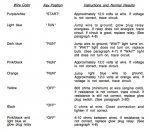
There are a few simple voltimeter actions listed in the instructions for testing the GPM that I don't grasp 100%. Does anyone mind elaborating on phrases like "Approximately 12.0 volts at wire","jump wire to ground","800 ohms at wire" (TM image is attached below). I'm assuming the first two use the voltage setting, and the last uses resistance, but where exactly am I placing my meter wires? thanks in advance.

Screen Shot 2016-03-28 at 7.19.39 PM.jpg
 

AECS

Member
305
3
18
Location
Munford, TN
Ill give it a shot, all reading will be with the red lead at the wire or terminal and the black at ground unless specified for a different position. Jumping the wire to ground just means to electricaly short it to ground, with a short length of wire, I have made a few jumpers with alligator clips on each end.
 

MarcusOReallyus

Well-known member
4,524
811
113
Location
Virginia
Ill give it a shot, all reading will be with the red lead at the wire or terminal and the black at ground unless specified for a different position. Jumping the wire to ground just means to electricaly short it to ground, with a short length of wire, I have made a few jumpers with alligator clips on each end.
Eggstackly right.

Just make sure that ground is a good ground. Alligator clips are your friends.
 

wisconsinz

Member
52
1
8
Location
Duluth, MN
So for the resistance am I connecting the red lead to the module terminal/wire and the black lead to the ground? If I'm getting readings that aren't correct should I get a new card or move to a different area? From the TM is sounds like module is the first place to start/replace. My main issue has always been cold starting, but lately its been giving me problems in 50 degree F weather. Turns over but takes forever to fire, and eventually will just drain the batts. Glow plugs are new and have good resistance, gp relay is clicking, wait lights working. Batts have been replaced as well. Maybe I should move on to testing fuel pressure?
 

MarcusOReallyus

Well-known member
4,524
811
113
Location
Virginia
So for the resistance am I connecting the red lead to the module terminal/wire and the black lead to the ground?


No, you use black on ground for the voltage readings. For resistance readings, the TM should tell you exactly where to connect the leads, and you need to have the batteries disconnected first.


Glow plugs are new and have good resistance, gp relay is clicking, wait lights working. Batts have been replaced as well. Maybe I should move on to testing fuel pressure?
No, not time to look at fuel yet. The GP relay is still suspect. It can click over but not conduct current to the GPs. The contacts can get burned. Test for voltage while someone turns on the GPs for you. You should see about 12v at the output (bottom lug) of the GP relay.

Check that and let us know what you get.
 

wisconsinz

Member
52
1
8
Location
Duluth, MN
Screen Shot 2016-03-28 at 7.19.39 PM.jpg

In the TM instructions for testing all the module wires it only tells you to disconnect pink injector pump wire and pull out the controller card...nothing about disconnecting batteries.

Here's what I'm getting as of now:

Purple/white: 7 volts
light blue: gp relay does energize
dark blue: wait light turns on
pink/black: 11 volts
orange: 4 volts
yellow: (still unsure how to proceed)
black: (still unsure how to proceed)
pink/black & light blue at gp relay: 14 ohms
 

MarcusOReallyus

Well-known member
4,524
811
113
Location
Virginia
Okay, I see what they are doing. First time I've looked at that section.

On the yellow, they call for 800 ohms, but don't specify anything about where, so they mean 800 ohms to ground. You are measuring the resistance from that wire to a good ground.

Same on the black wire.

On the last one, you are measuring between two connections on the GP relay out on the firewall.
 

wisconsinz

Member
52
1
8
Location
Duluth, MN
Thanks for all the help yall.

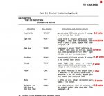
So, I'm pretty confident I've tested this correctly with my multimeter. I've attached a picture of the TM's testing procedure with the results I'm getting in red.
gp test copy.jpg

The GP relay test seems to be good, though. (there is no voltage getting to the orange lead on the GP relay when the key is turned to off. When it's turned to "run" the voltage hangs out around 6.8 volts for about 23 seconds before the relay clicks, then down to 0 volts.

The resistors resistance seems to be correct as well. (supposed to be .28 ohms and my meter read .3)

The GPs all read 1 ohm.

Since I have a reading of 1 for my resistance at yellow wire of GP module (temp sensor), I traced the circuit and the wires seem to be fine and the sensor looks like it's a newer style. Does anyone know how to remove the wires from the sensor? I'd like to check for continuity just to be positive. 20160404_190007.jpg If I'm still not getting 800 ohms, I will replace it.


With these results should I just do a resistor bypass? Any suggestions? Thanks again!
 

antennaclimber

Moderator
Moderator
Steel Soldiers Supporter
1,353
895
113
Location
State College, PA
6.8 volts is low. It should be much closer to 12 volts.

What is the voltage on the other big terminal (on the relay) in the RUN position?
 

tim292stro

Well-known member
2,118
39
48
Location
S.F. Bay Area/California
Thanks for the PM. Just from a quick read, it's starting to sound like a bad GP relay, or bad fusible link. It looks like most of the measurements you've taken are good. Can you do a sanity check?

Measure the voltage from one large GP terminal to the other GP terminal. When the truck is off you should see about 24.5V between these terminals - the relay connection is open (inactive), so you are in effect measuring from the battery to ground.

When you turn the key to run on a cold truck, you should hear a "click" from the relay and measure about 0V between those terminals - the relay is closed (active), so the relay is acting like a simple piece of wire and there should be no appreciable difference between one terminal and the other. IF you do see more than 0.5V across that relay you need to replace it, that voltage is a sign of resistance (wear) and resistance makes heat. That relay can weld itself "on" if the contacts get hot.

Now, if you don't see a voltage across the relay, and you're still seeing less than half the system voltage at the glow plugs, then you have another resistance in the circuit. The most likely cause is going to be fusible links. There are two fusible links after the GP relay, and before each of the two thick orange wires splits off into four (each) smaller green wires. Fusible links are designed to burn open if hey get overloaded without burning all the way through the jacket, and many fail partially melted, so they measure "good" with a simple continuity test, but will not support their rated load any more.

I have mentioned before that I have a spotlight with alligator clips instead of a lighter plug, this is my test light for load circuits with a fusible link. A 130Watt 12V bulb draws a full 10Amps, which is about half what a cold glow plug draws. If the spotlight only lights up dim, I immediately suspect the fusible link. I am using this tester on a 12V GP system (Roscommon mod), if you use this method on a 24V system you may find your lightbulbs exploding...
 

antennaclimber

Moderator
Moderator
Steel Soldiers Supporter
1,353
895
113
Location
State College, PA
Last edited:

wisconsinz

Member
52
1
8
Location
Duluth, MN
Measure the voltage from one large GP terminal to the other GP terminal. When the truck is off you should see about 24.5V between these terminals - the relay connection is open (inactive), so you are in effect measuring from the battery to ground.

When you turn the key to run on a cold truck, you should hear a "click" from the relay and measure about 0V between those terminals - the relay is closed (active), so the relay is acting like a simple piece of wire and there should be no appreciable difference between one terminal and the other. IF you do see more than 0.5V across that relay you need to replace it, that voltage is a sign of resistance (wear) and resistance makes heat. That relay can weld itself "on" if the contacts get hot.
So I measured the voltage between main gp relay terminals (one prong on orange lead, and one on red lead) and it was around 24 volts with the car off and cold. I'm assuming I was supposed to do this with the controller card in? After I turned the ignition to "run" it went to 0 volts. Then after about 20 seconds the relay clicked and it went to around 12 volts. Is this what it should have done?

This thread shows what can happen inside the GP relay. After the relay was replaced, I added a 2nd voltmeter to monitor the voltage to the glow plugs with a second voltmeter. Post#29 shows pictures of the additional voltmeter.
Where is the first voltmeter?
 

tim292stro

Well-known member
2,118
39
48
Location
S.F. Bay Area/California
So I measured the voltage between main gp relay terminals (one prong on orange lead, and one on red lead) and it was around 24 volts with the car off and cold. I'm assuming I was supposed to do this with the controller card in? After I turned the ignition to "run" it went to 0 volts. Then after about 20 seconds the relay clicked and it went to around 12 volts. Is this what it should have done?
Yes, with the GP card in. 24V off and 0V on is good, but when it clicked into the "resting"/off position after the warm-up it should have jumped back to 24V. That smells fishy, and not in a dinner is served kinda way, by not jumping all the way back to 24V, it tells me your GP relay is not fully releasing. Try the test again, and then if the voltage stays at 12V when it clicks off, give it a whack and see if the voltage goes all the way back up to 24V. If that works, you need a new GP relay.

Oh and slightly depressing news if that's the case, you will want to recheck each of your glow plugs, and they may have been damaged by extended run time from the relay not turning off when the GP card commands it.


Where is the first voltmeter?
In the dash board where the AC vents go (same side as the shifter column). What he did was add a voltmeter that reads only the GP voltage when active, if you've read the Master's Thesis on GP cascade failure, you understand that as your glow plugs begin to fail, the voltage climbs higher and higher from the normal 12V. This second voltmeter lets the vehicle operator view the condition of the pre-heat system during normal operation of the vehicle. Kind of what my idiot light GP switch you asked about in the PM is supposed to do in a more "go/no-go" fashion.


From the PM: Sorry, I didn't mean to distract you with the spotlight GP circuit tester, really we need to rule out the GP relay first. In the various years I've been working with CUCV GP systems on other people's vehicles (and diagnosing over the forums) and now working with my own CUCV - I have yet to come across a bad fusible link on the GP circuit. Start with the mechanical things that have a limited design life, then work your way into the wiring. In my experience, the wiring problems themselves come from people doing things to the wiring because they assume a device that clicks when it supposed to is working fine (and it may be the actual problem).

Keep working the problem, we have yet to find one on the GP system that will totally defeat the person asking, but understand: We are working with your words. We as helpers on the forum have to feel out what you know and understand based on how you describe it, and then translate that into what we know and understand, and then we have to come up with a solution or experiment to move forwards and translate it back to you in a way you understand. It may take some time and frustration on both parties behalfs, I don't think we're doing that bad a job personally (you included BTW) [thumbzup].
 

wisconsinz

Member
52
1
8
Location
Duluth, MN
Again, many thanks yall.

Oh and slightly depressing news if that's the case, you will want to recheck each of your glow plugs, and they may have been damaged by extended run time from the relay not turning off when the GP card commands it.
So, I will want to do another resistance test or actually remove each plug to check for swelling/damage?
 
Top