• Steel Soldiers now has a few new forums, read more about it at: New Munitions Forums!

  • Microsoft MSN, Live, Hotmail, Outlook email users may not be receiving emails. We are working to resolve this issue. Please add support@steelsoldiers.com to your trusted contacts.


Throttle Position Sensor test cable pinout - anyone have this?

TruckGuy

Member
Steel Soldiers Supporter
140
23
18
Location
Belmont, NC
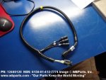
Does anyone have the pinout for the TPS test cable or a cable they can check? Or maybe a cable they are willing to lend out?

TPS cable P# 12460120 6150-01-412-7774
 

FlameRed

Well-known member
Steel Soldiers Supporter
283
429
63
Location
Florida
Here is what I used. From US Shift:

Identifying the Terminals of an Unknown TPS

This is a procedure for identifying the correct terminal connections of any potentiometer-style throttle position sensor (almost all three-terminal TP sensors). A DVOM or analog Ohmmeter is required.

  1. Set the meter to resistance mode and set it to a scale that can read up to 10K or 20K Ohms (if it is not auto-ranging). Please keep in mind when setting up and reading the meter that "K" means thousands of Ohms. In other words, 15K Ohms is the same as 15,000 Ohms.
  2. Connect the meter to two pins at a time while operating the lever or cam of the TPS. Watch the meter while rotating the sensor. Check all three pairs of pins until you find a pair that does not change resistance when you rotate the sensor. The two pins that do not change resistance are the fixed ends of the resistance element (+5V and ground). The remaining pin that did change is known as the "wiper". It is the moving contact that slides along the resistance element to give the varying voltage. This is the output terminal of the sensor and should be connected to our green wire (Vehicle pin 3).
  3. Next, with the sensor at the idle or closed throttle position, measure the resistance between the wiper (output) and each of the end terminals (the two whose resistance did not change in step 2) of the sensor. The end terminal with the lowest resistance to the wiper (at idle) is the ground terminal, and should connect to the black main ground wire of the TCS (Vehicle pin 16). The terminal with the higher resistance to the wiper is the 5 volt reference input to the sensor and should connect to the orange wire (Vehicle pin 11) in our harness.
 

TruckGuy

Member
Steel Soldiers Supporter
140
23
18
Location
Belmont, NC
FlameRed,
Definitely good info in pinning out the TPS itself. Thanks for the help.

But, What I'm looking for is the pinout for the test cable used to adjust the TPS. ( Yes guys, I know you can adjust it to "good enough" without the cable or the block.)

The cable looks like this....


12460120_6150-01-412-7774_750238.jpg
 
Top
AdBlock Detected

We get it, advertisements are annoying!

Sure, ad-blocking software does a great job at blocking ads, but it also blocks useful features of our website like our supporting vendors. Their ads help keep Steel Soldiers going. Please consider disabling your ad blockers for the site. Thanks!

I've Disabled AdBlock
No Thanks