• Steel Soldiers now has a few new forums, read more about it at: New Munitions Forums!

  • Microsoft MSN, Live, Hotmail, Outlook email users may not be receiving emails. We are working to resolve this issue. Please add support@steelsoldiers.com to your trusted contacts.


Trouble connecting the thermostatic fan switch

85
56
18
Location
Parma, Italy
I have a 6.2 M998, previous owner thought that bypassing the thermostatic switch and replacing it with a common manual switch was a good idea, while also removing the thermostat
Now I’m working on re-installing everything back to factory spec, but I’m having a bit of a hard time understanding where the thermostatic switch has to be connected, I know it’s a 458 wire but is it A, B, C or D?
The manual switch that the owner installed is currently connected to 458B and 458D, are those two the correct one for the thermostatic switch as well?

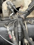
In the picture, the two wires going to the top right, outside of the harness, are the ones going to the manual switch
 

Attachments

Coug

Well-known member
Steel Soldiers Supporter
2,842
4,065
113
Location
Olympia/WA
This thread has a large image of the wiring diagram. It might be easier to follow the wiring in it than the regular manual. It's labeled as the ambulance, but engine wiring should all be the same.


looking at the diagram, the fan temp switch is connected to 458 A and 458 B
Typically in circuits the letters show where in the circuit the wire is, so you will usually see the letters progress as you go through the circuit.
I don't see 458D in the diagram; 458A comes from 583A and the glow plug controller as a voltage source. 458A goes to the fan temp switch, then 458B goes from the fan temp switch to the time delay module. The time delay module then controls the operation of the cavillac valve/fan clutch solenoid.
 
Last edited:
85
56
18
Location
Parma, Italy
This thread has a large image of the wiring diagram. It might be easier to follow the wiring in it than the regular manual. It's labeled as the ambulance, but engine wiring should all be the same.


looking at the diagram, the fan temp switch is connected to 458 A and 458 B
Typically in circuits the letters show where in the circuit the wire is, so you will usually see the letters progress as you go through the circuit.
I don't see 458D in the diagram; 458A comes from 583A and the glow plug controller as a voltage source. 458A goes to the fan temp switch, then 458B goes from the fan temp switch to the time delay module. The time delay module then controls the operation of the cavillac valve/fan clutch solenoid.
Just took a look at those wiring diagrams and yes, can't find a 458D neither, so I have no idea where the previous owner got that from
 

DREDnot

Well-known member
717
430
63
Location
Phoenix, AZ
Plug the FTS into 458a and 458d and it should function as intended.

Personally i would leave the manual override switch inline as a convenient bypass for manual activation
 
85
56
18
Location
Parma, Italy
Plug the FTS into 458a and 458d and it should function as intended.

Personally i would leave the manual override switch inline as a convenient bypass for manual activation
That’s what I did, I put the thermostatic switch and the manual switch in line so it the engine is overheating and the thermostatic switch fails, I can still engage the fan manually by breaking the circuit
 
Top
AdBlock Detected

We get it, advertisements are annoying!

Sure, ad-blocking software does a great job at blocking ads, but it also blocks useful features of our website like our supporting vendors. Their ads help keep Steel Soldiers going. Please consider disabling your ad blockers for the site. Thanks!

I've Disabled AdBlock
No Thanks