"I think we are all on the same page, just trying to get the terminology to sync up." --------------- RIGHT
"Generally there should only be one location where the neutral and ground are bonded together." ------------ RIGHT
"If your house is like mine and has the neutral/ground bond in the house panel then the generator must not have the neutral/ground bond even if the transfer switch disconnects all four utility wires as the house panel is where the neutral/ground bond exists." -------------- YES and NO, neutral and ground bond in the primary breaker panel in the house yes, transfer switch disconnects 3 wires comming in from the utility - 1 neutral, 2 hots.
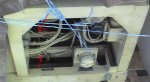
The way I have my house rigged is (just follow along) - there are three wires comming in off the pole/meter one is neutral and two are hot. These three wires will now go into an on/off switch, all three. Then on the other side of the switch are the corresponding three that go into the top of the xfer switch. The bottom of the xfer switch has genny 2 hots and 1 neutral. The house is grounded to the steel water pipe with a bare copper wire. This is connected to the main breaker body, jumped to the xfer body, and jumped to the incomming switch body, and connected to the genny ground which is also attached to an immediat ground rod at the trailer. So then the bottom of the xfer switch output has 1 neutral and 2 hots which the 2 hots go to the main double circut breaker and the neutral output goes to the main neutral buss in the main panel which is also the only point where THE GROUND is attached. The water pipe wire and the genny and the connected box body grounds are all combined and here and only here are attached to the neutral in the main neutral/ground bus bar where all the house grounds and neutrals are together. Elswhere in the house all the neutrals and grounds are seperate. I don't know everything about the internal wiring inside the gennys so if there is a connection with the neutrals and grounds IN the unit, it is news to me. As far as I know there isn't, thats why the rigs have a ground stud on the frame which is jumped to the trailer which I double jump to a ground rod and the ground to the xfer switch. No hard feelings, I love this stuff and if I can learn and share then we're good!